GE Power Management 745 Transformer Management Relay 5-91
5 SETPOINTS 5.9 TIME OVERCURRENT CURVES
5
5.9 TIME OVERCURRENT CURVES 5.9.1 NOTE
Graphs of time-current curves on 11”x17” log-log graph paper are available upon request.
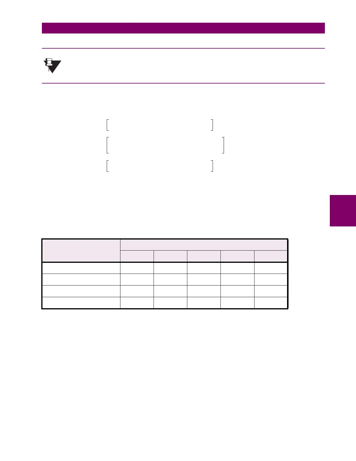
5.9.2 ANSI CURVES
The ANSI time overcurrent curve shapes conform to industry standard curves and fit into the ANSI C37.90
curve classifications for extremely, very, normally, and moderately inverse. The 745 ANSI curves are derived
from the following formula:
where:
T
= Operate Time (seconds)
M
= Multiplier setpoint
I
= Input Current
I
pkp
= Pickup Current setpoint
A
,
B
,
C
,
D
,
E
= Constants
Table 5–10: ANSI CURVE CONSTANTS
ANSI CURVE SHAPE CONSTANTS
A B C D E
EXTREMELY INVERSE 0.0399 0.2294 0.5000 3.0094 0.7222
VERY INVERSE 0.0615 0.7989 0.3400 –0.2840 4.0505
NORMALLY INVERSE 0.0274 2.2614 0.3000 –4.1899 9.1272
MODERATELY INVERSE 0.1735 0.6791 0.8000 –0.0800 0.1271
NOTE
T
MA
B
1.03
C
–
----------------------
D
1.03
C
–
()
2
-----------------------------
E
1.03
C
–
()
3
-----------------------------
++ + , for 1
I
I
pkp
---------
1.03
<≤×
MA
B
II
pkp
⁄
C
–
-------------------------
D
II
pkp
⁄
C
–
()
2
---------------------------------
E
II
pkp
⁄
C
–
()
3
---------------------------------
++ + , for 1.03
I
I
pkp
--------- 20.0
<≤×
MA
B
20.0
C
–
----------------------
D
20.0
C
–
()
2
-----------------------------
E
20.0
C
–
()
3
-----------------------------
++ + , for
I
I
pkp
--------- 20.0
≥×
=

 Loading...


