GE Power Management 745 Transformer Management Relay 5-61
5 SETPOINTS 5.6 S4 ELEMENTS
5
The issue of maloperation due to heavy external faults resulting in CT saturation is handled by a programma-
ble timer. The timer provides the necessary delay required for the external fault to be cleared by the appropri-
ate external protection with the added benefit that if the RGF element remains picked up after the timer expires
the 745 will operate and clear the fault. This approach provides backup protection. Since the RGF element is
targeted at detecting low magnitude internal winding fault currents, the time delay for internal faults is of little
consequence since sensitivity and security are the critical parameters.
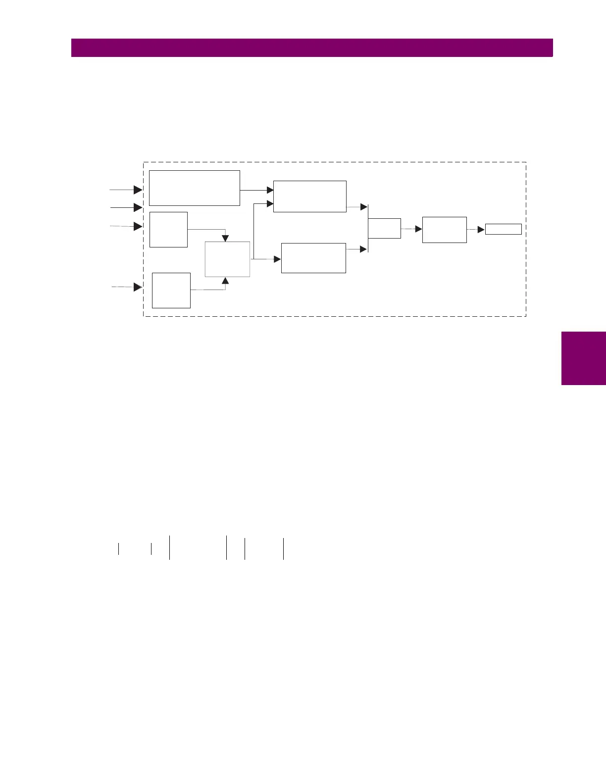
Figure 5–13: RESTRICTED GROUND FAULT IMPLEMENTATION
b) RESTRICTED GROUND FAULT SETTINGS EXAMPLE
Consider a transformer with the following specifications:
10 MVA, 33 kV to 11 kV, 10% Impedance, Delta/Wye30
Rg
= 6.3 ohms
CT Ratio = 600 / 1 Amp
Rated Load Current =
I
rated
= 10 MVA / (
√
3 x 11 kV) = 525 Amps
Maximum Phase-to-Ground Fault Current =
I
gf(max)
= 11 kV / (
√
3 x 6.3) = 1000 Amps
For a winding fault point at 5% distance from the neutral:
From Figure 5–11: FAULT CURRENTS VS. FAULT POINT FROM NEUTRAL on page 5–60, we see that the
I
p
increase due to the fault is negligible and therefore 3
I
o
= 0 (approx.)
Therefore: maximum phase current =
I
max
=
I
rated
= 525 A (approx.), and
Measure
Ig
Calculate
3I
o3Io
Slope = I /Igd maxSlope = I/Igd max
Slope > SetpointSlope > Setpoint
Timer
0 to 0.5s0
to 0.5s
Ia
Ib
Ig
Ic
Calculate
Maximum PhaseMaximum
Phase
Current
Imax
Calculate
|3I - I |
og|3I - I|og
I > SetpointgdI>Setpointgd
IgdIgd
AND
OUTPUT
745
I
fault
0.05
I
gf max
()
×
0.05 1000 A
×
50 A===
I
gd
3
I
0
I
g
– 0
I
fault
CT Ratio
-----------------------
– 0
50 A
600
------------
– 0.08 CT
×
Pickup Setting== = = =
Slope
I
gd
I
max
-----------
50 A
525 A
----------------
9.5% (select Slope Setting = 9%)== =
Time Delay: dependent on downstream protection coordination (100 ms typical)

 Loading...


