10-16 745 Transformer Management Relay GE Power Management
10.6 PROTECTION SCHEMES 10 COMMISSIONING
10
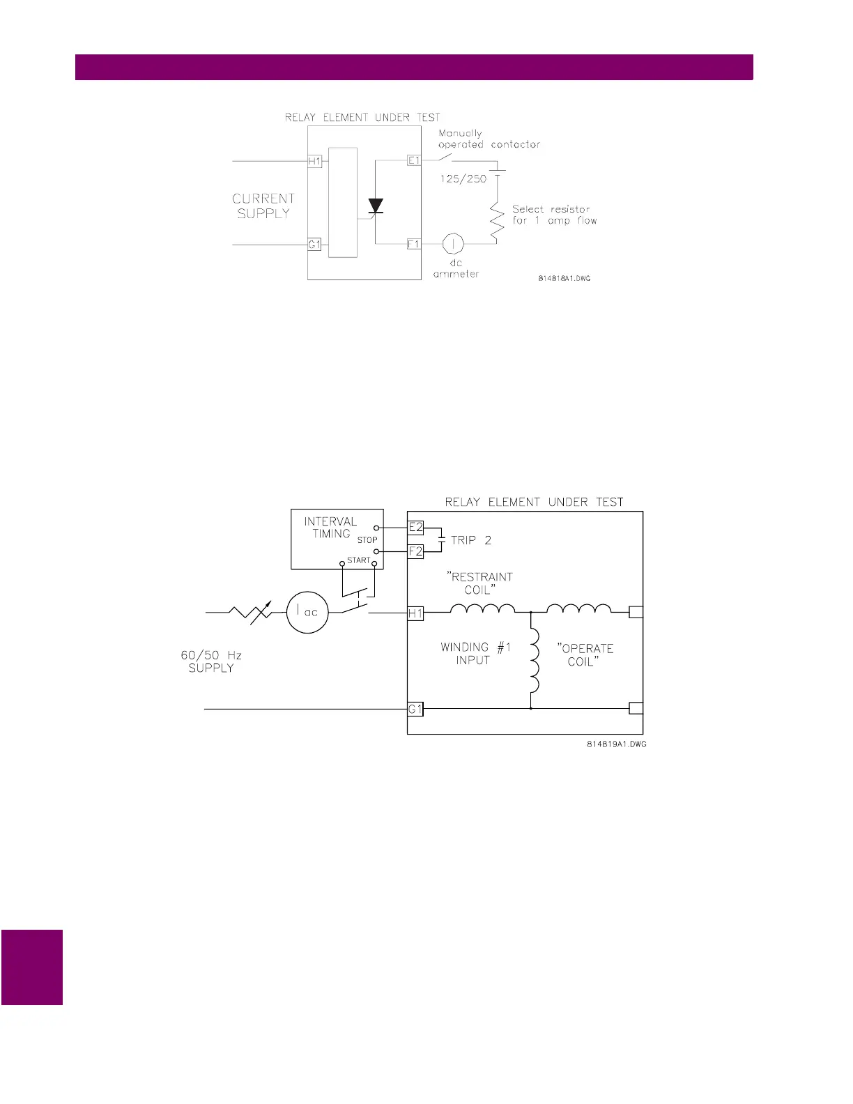
Figure 10–4: SOLID STATE OUTPUT TEST CIRCUIT
e) BASIC OPERATING TIME
1. To measure the basic operating time of the harmonic restrained differential elements, connect an AC cur-
rent signal to terminals H1 and G1, through a double-pole single-throw switch. The second pole of the
switch starts a timer circuit which is stopped by the operation of the relay trip contact. Refer to the figure
below for details.
2. Close the switch and set the current level to 3 times the minimum pickup value measured earlier. Re-open
the switch and reset all targets on the relay. Ensure that timer circuit functions correctly.
3. Close the switch and record operating time of relay.
Figure 10–5: TIMER TEST CIRCUIT
f) SLOPE MEASUREMENTS
The auto configuration processes the currents to correct for phase shifts, CT mismatch, and zero sequence
component removal. As such, it more complex to measure the slope from an external single phase injection.
Therefore, the use of displayed actual values is recommended.
The differential and restraint currents are displayed the actual values sections:
ACTUAL VALUES/A2 METERING/CURRENTS/DIFFERENTIAL/PHASE A DIFFERENTIAL CURRENT
ACTUAL VALUES A2 METERING/CURRENTS/RESTRAINT/PHASE A RESTRAINT CURRENT

 Loading...


