5-40 745 Transformer Management Relay GE Power Management
5.4 S2 SYSTEM SETUP 5 SETPOINTS
5
5.4.9 ANALOG INPUT
The 745 provides a general purpose DC current input for use in monitoring any external parameter. Any stan-
dard transducer output may be connected to the analog input for monitoring.
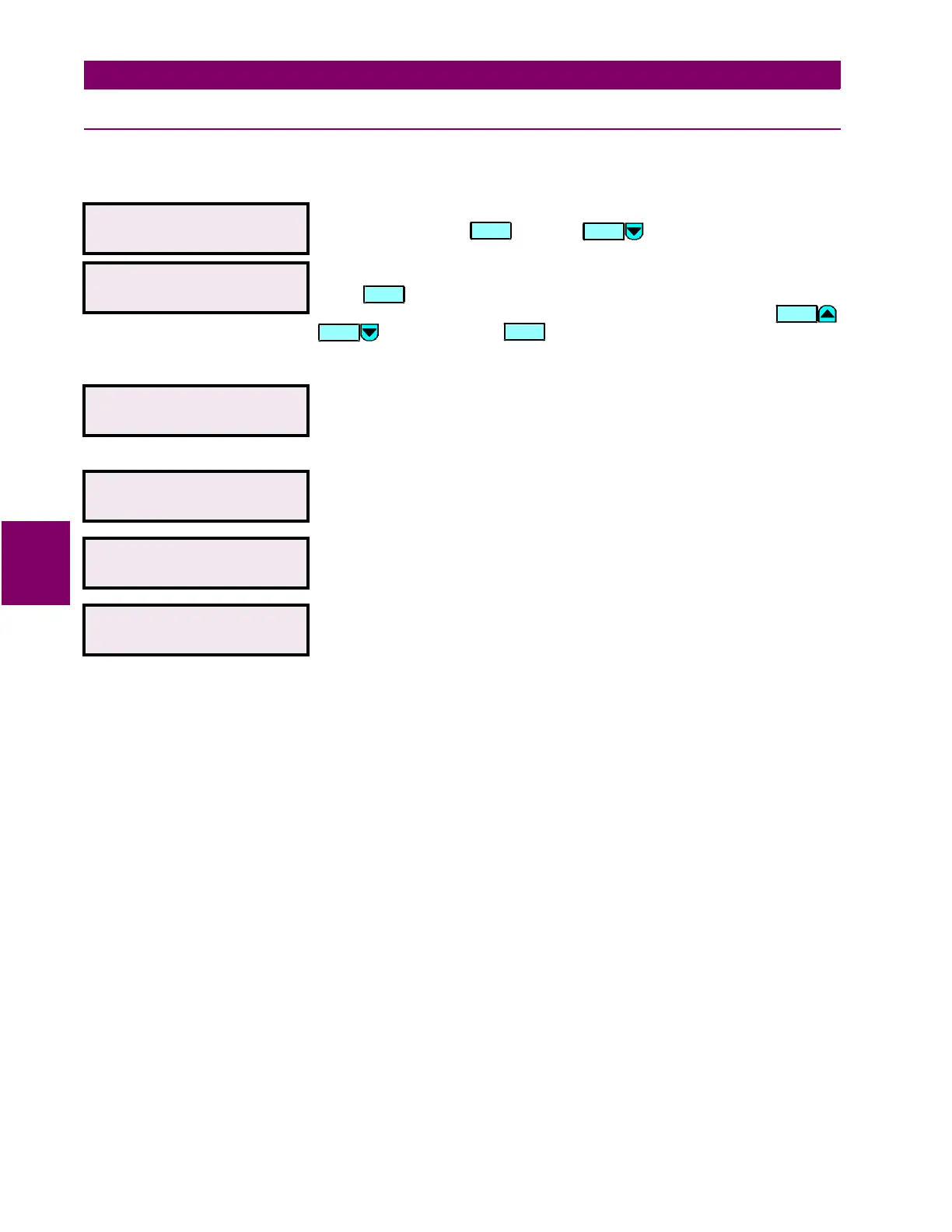
y ANALOG INPUT
y [ENTER] for more
This message indicates the start of the
ANALOG INPUT
section. To continue
these setpoints press , or press to go to the next section.
ANALOG INPUT NAME:
ANALOG INPUT
Range: 18 alphanumeric characters
Press to begin editing the name of the analog input. The text may be
changed from
ANALOG INPUT
one character at a time, using the /
keys. Press the key to store the edit and advance to the
next character position. This name will appear in the actual value message
A2 METERING/ANALOG INPUT
.
ANALOG INPUT UNITS:
µ
A
Range: 6 alphanumeric characters
Enter the units of the quantity being read by editing the text as described
above. The 6 characters entered will be displayed instead of
Units
wherever
the analog input units are displayed.
ANALOG INPUT RANGE:
0-1 mA
Range: 0-1 mA / 0-5 mA / 4-20 mA / 0-20 mA
Select the current output range of the transducer that is connected to the
analog input.
ANALOG INPUT MINIMUM
VALUE: 0
µ
A
Range: 0 to 65000 (steps of 1)
Enter the value of the quantity measured which corresponds to the minimum
output value of the transducer.
ANALOG INPUT MAXIMUM
VALUE: 1000
µ
A
Range: 0 to 65000 (steps of 1)
Enter the value of the quantity measured which corresponds to the
maximum output value of the transducer.
ENTER
MESSAGE
ENTER
VALUE
VALUE

 Loading...


