GE Power Management 745 Transformer Management Relay 5-9
5 SETPOINTS 5.2 AUTO-CONFIGURATION
5
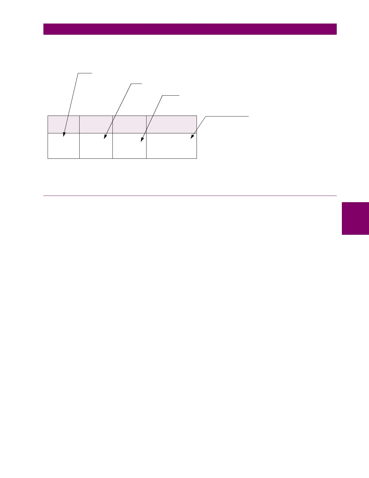
As shown in the ‘Y/d30
°
’ entry of the table of transformer types, the phase angle correction (or phase shift)
introduces 30
°
lag in Winding 1. This lag is described in Table 5–2: PHASE SHIFTS on page 5–23. This table
provides the following information about each phase shift type:
5.2.6 ZERO-SEQUENCE COMPONENT REMOVAL
1. If zero-sequence current can flow into and out of one transformer winding (e.g. a grounded Wye or zig-zag
winding) but not the other winding (e.g. a Delta winding), external ground faults will cause the differential
element to operate incorrectly. Traditionally, this problem is solved by Delta connecting the CTs on the Wye
side of a Wye/Delta transformer so that the currents coming to the relay are both phase corrected and void
of zero-sequence current. Because the 745 software mimics the CT Delta connection, the zero-sequence
current is automatically removed from all Wye or zig-zag winding currents of transformers having at least
one delta winding.
2. External ground faults also cause maloperation of the differential element for transformers having an in-
zone grounding bank on the Delta side (and the Wye connected CTs on the same side). Traditionally, this
problem is solved by inserting a zero-sequence current trap in the CT circuitry. The 745 automatically
removes zero-sequence current from all Delta winding currents when calculating differential current.
Where there is no source of zero-sequence current (e.g. Delta windings not having a grounding bank), the
745 effectively removes nothing.
3. Autotransformers have an internal tertiary winding to provide a path for third-harmonic currents and control
transient overvoltages. Also, many two-winding Wye/Wye transformers have a three-legged core construc-
tion that forces zero-sequence flux into the transformer tank, creating an inherent Delta circuit. In both
these cases, there is zero-sequence impedance between the primary and secondary windings. The 745
removes zero-sequence current from all windings of Wye/Wye and Wye/Wye/Wye transformers to prevent
possible relay maloperations resulting from these two conditions.
PHASE
SHIFT
INPUT
PHASORS
OUTPUT
PHASORS
PHASOR
TRANSFORMATION
30° lag a = (A – C) /
√
3
b = (B – A) /
√
3
c = (C – B) /
√
3
the phasors after the phase shift is applies (a/b/c/)
the phasors before the phase shift is applied (A/B/C)
the phase shift as it appears in the table of transformer types
the equations used to achieve the
phase shift (A/B/C → a/b/c)

 Loading...


