8-12 745 Transformer Management Relay GE Power Management
8.2 MODBUS PROTOCOL 8 COMMUNICATIONS
8
A SCADA system polls the Total Number of Trace Triggers register once every minute. It now reads a value of
6 from the register when previously the value was 5, which means that one new trigger has occurred during the
last minute. The SCADA system writes a value of 6 to the Trace Buffer Selector Index register. It then writes
the value of 0 to the Trace Channel Selector Index register, reads the waveform data for Winding 1 Phase A
Current of trace buffer 6 from the Trace Memory Data registers and stores the data to permanent memory for
retrieval by an operator. The SCADA system now writes the value 1 to the Trace Channel Selector Index and
then reads the waveform data for Winding 1 Phase B Current. The SCADA system continues by writing all
other channel numbers to the Trace Channel Selector Index, each time reading the waveform data, until all
channels for buffer 6 have been read. All the waveform data for the new trace memory trigger has now been
retrieved by the SCADA system, so it resumes polling the Total Number of Trace Triggers register.
8.2.16 ACCESSING DATA VIA THE USER MAP
The 745 has a powerful feature, called the User Map, which allows a computer to access up to 120 non-con-
secutive registers (setpoints or actual values) by using one Modbus read message.
It is often necessary for a master computer to continuously poll various values in each of the connected slave
relays. If these values are scattered throughout the memory map, reading them would require numerous trans-
missions and would labor the communication link. The User Map can be programmed to join any memory map
address to one in the block of consecutive User Map locations, so that they can be accessed by reading (and
writing to, if joined to setpoints) these consecutive locations.
The User Map feature consists of:
1. User Map Addresses #1 to #120 (located at memory map addresses 0180 to 01F7 hex). These are the
setpoints which store the (possibly discontinuous) memory map addresses of the values that are to be
accessed.
2. User Map Values #1 to #120 (located at memory map addresses 0100 to 0177 hex). These are the access
points of the remapped locations. Reading User Map Value #1 returns the value at the address stored in
User Map Address #1, User Map Value #2 the value at User Map Address #2, and so on. Writing to any
User Map Value is only possible if the address stored in the corresponding User Map Address is that of a
setpoint value.
For an example of how to use the User Map feature, say the master computer is required to continuously read
the memory map locations shown in the table below from slave 11. Normally, this would require at least 4 sep-
arate master query messages.
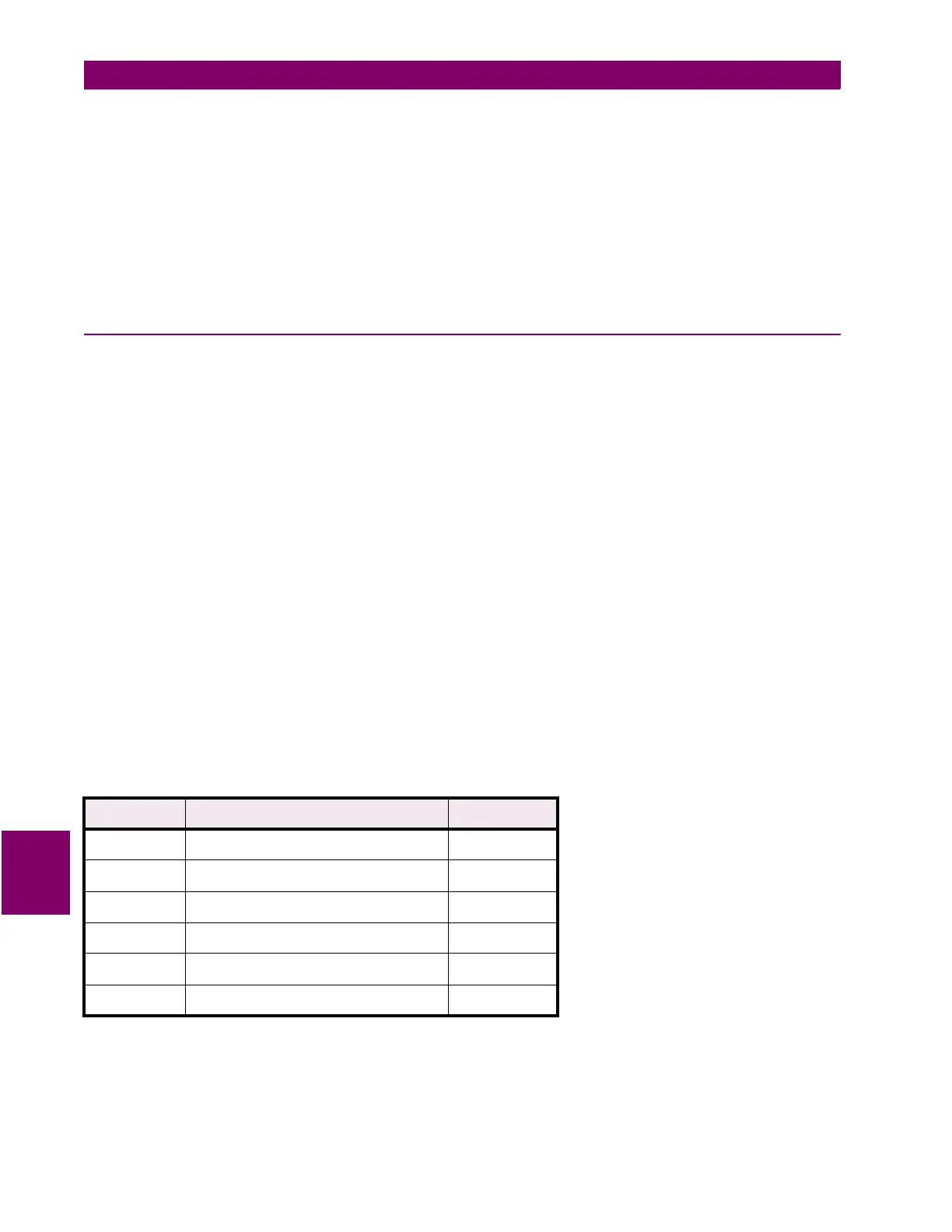
Table 8–4: MEMORY MAP LOCATIONS TO BE ACCESSED
ADDRESS DESCRIPTION TYPE
0200H Relay Status actual value
0210H W3 Phase Time O/C Flag actual value
0300H W1 Phase A 4th Harmonic Content actual value
0301H W1 Phase B 4th Harmonic Content actual value
0302 hex W1 Phase C 4th Harmonic Content actual value
2002 hex Percent Differential Pickup setpoint
 Loading...


