GE Power Management 745 Transformer Management Relay 5-23
5 SETPOINTS 5.2 AUTO-CONFIGURATION
5
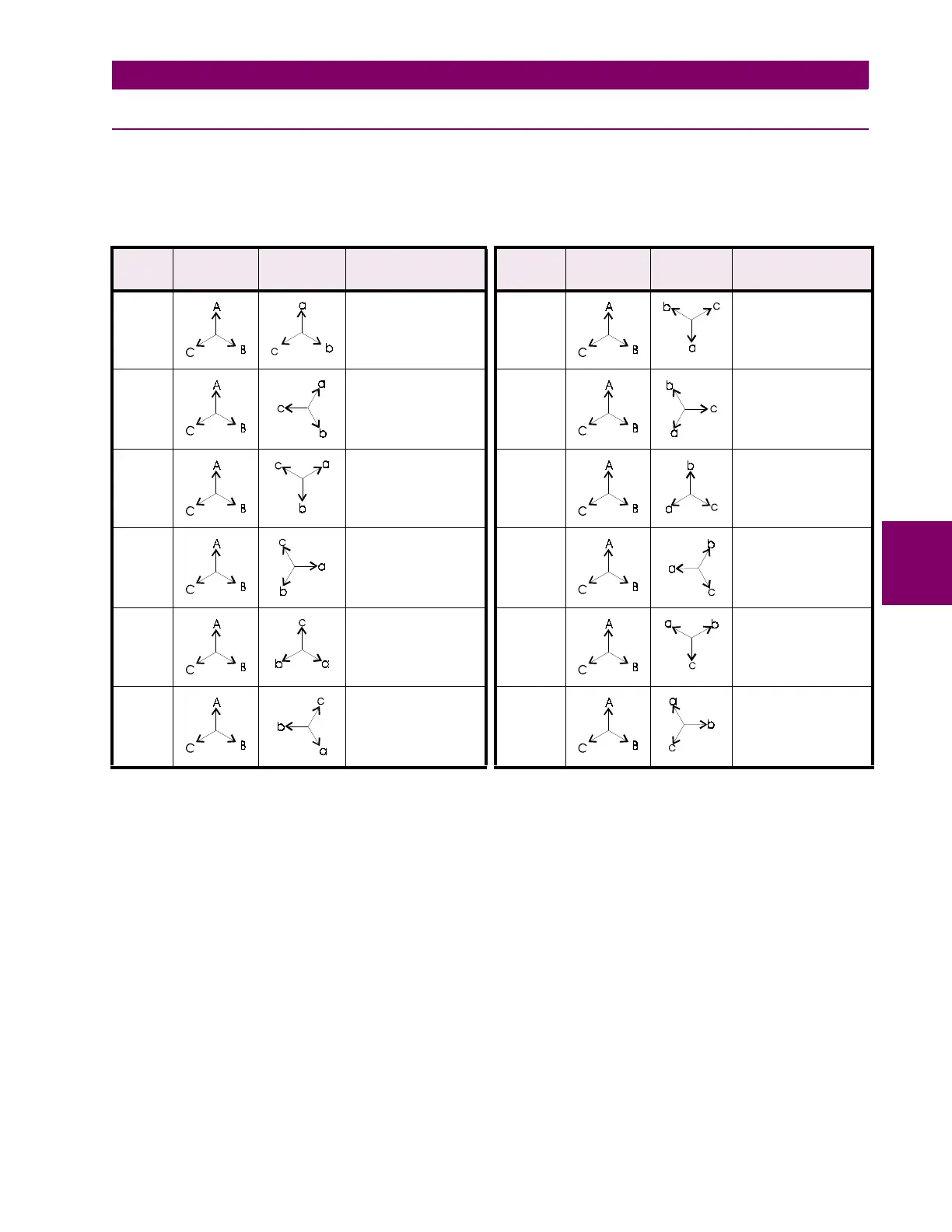
5.2.8 TABLE OF PHASE SHIFTS
This table provides additional information about the Phase Shift column in Table 5–1: TRANSFORMER
TYPES on page 5–10 and represents an assumed ABC phasor rotation. For transformers connected to a sys-
tem with a phasor rotation of ACB, interchange all B (b) and C (c) designations.
Table 5–2: PHASE SHIFTS
PHASE
SHIFT
INPUT
PHASORS
OUTPUT
PHASORS
PHASOR
TRANSFORMATION
PHASE
SHIFT
INPUT
PHASORS
OUTPUT
PHASORS
PHASOR
TRANSFORMATION
0° a = A
b = B
c = C
180° lag a = –A
b = –B
c = –C
30° lag a = (A – C) /
√
3
b = (B – A) /
√
3
c = (C – B) /
√
3
210° lag a = (C – A) /
√
3
b = (A – B) /
√
3
c = (B – C) /
√
3
60° lag a = –C
b = –A
c = –B
240° lag a = C
b = A
c = B
90° lag a = (B – C) /
√
3
b = (C – A) /
√
3
c = (A – B) /
√
3
270° lag a = (C – B) /
√
3
b = (A – C) /
√
3
c = (B – A) /
√
3
120° lag a = B
b = C
c = A
300° lag a = –B
b = –C
c = –A
150° lag a = (B – A) /
√
3
b = (C – B) /
√
3
c = (A – C) /
√
3
330° lag a = (A – B) /
√
3
b = (B – C) /
√
3
c = (C – A) /
√
3

 Loading...


