GE Power Management 745 Transformer Management Relay 10-21
10 COMMISSIONING 10.6 PROTECTION SCHEMES
10
c) TARGET, OUTPUT CONTACT, & DISPLAY OPERATION
Verify the correct operation of all targets and output contacts and display messages during testing.
d) BLOCKING FROM LOGIC INPUTS
Each element is programmable to be blocked by a logic input, virtual input, virtual output, output relay opera-
tion, or self-test relay operation. This test verifies that the differential element can be blocked by Logic Input 1.
1. Select logic input 1 as shown below:
SETPOINTS/S4 ELEMENTS/INST DIFFERENTIAL/INST DIFFERENTIAL BLOCK:
Logc Inpt 1
2. Apply current to operate the differential element then assert Logic Input 1. Verify that the element has reset
and that all targets can be reset.
3. With Logic Input 1 asserted, remove the current and reapply. Verify that the element did not operate.
10.6.4 PHASE TIME OVERCURRENT
This procedure verifies that the phase time overcurrent element performance matches the in-service settings.
Since these elements can have any one of a multitude of timing curves, a table of expected operating times
versus applied current should be prepared prior to testing the elements. Refer to Section 5.9: TIME OVER-
CURRENT CURVES on page 5–91 for information on timing curves.
If the relay elements are set for a "Linear" reset characteristic when measuring the operating times, ensure that
there is sufficient time between test current injections for the element to reset fully; otherwise, erroneous timing
measurements will be obtained.
The settings for these elements are found under:
SETPOINTS/S4 ELEMENTS/PHASE OC/W1..., W2..., W3...
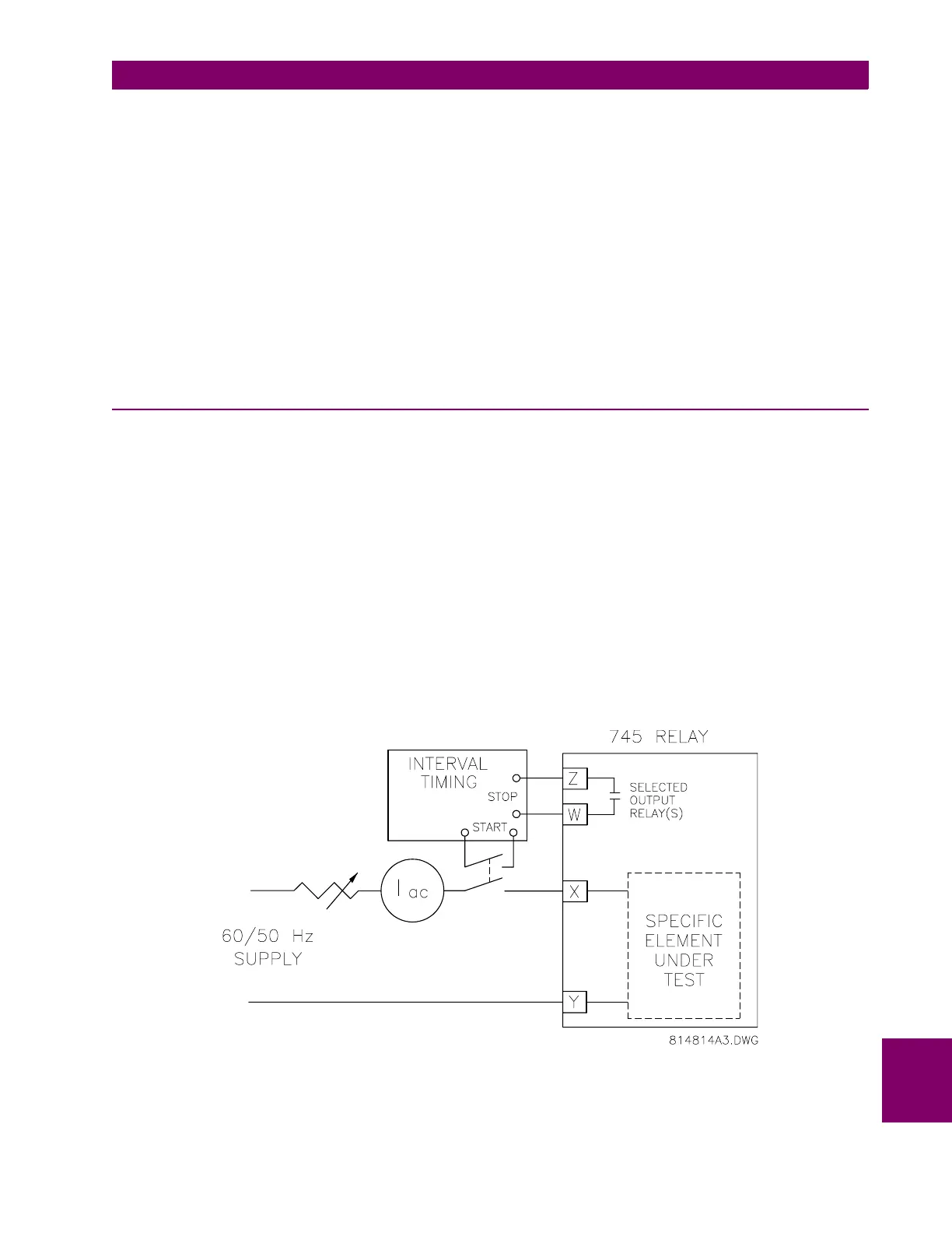
a) WINDING #1 ELEMENTS
To ensure that only the Phase Time overcurrent elements operate the trip relays (and any other output relays)
selected by the logic, disable all protection features except Phase Time Overcurrent. Use the general test
setup shown below:
Figure 10–9: GENERAL TEST SETUP
Connect the current supply to terminals X = H1 and Y = G1 to test the Winding 1 A-phase element. Monitor the
appropriate output relays per the FlexLogic settings.

 Loading...


