5-52 745 Transformer Management Relay GE Power Management
5.6 S4 ELEMENTS 5 SETPOINTS
5
5.6.5 INSTANTANEOUS DIFFERENTIAL
This section contains the settings to configure the (unrestrained) instantaneous differential element, for protec-
tion under high magnitude internal faults.
5.6.6 PHASE OVERCURRENT
This section contains settings to configure the phase overcurrent elements. Included are phase time overcur-
rents and two levels of phase instantaneous overcurrent for each phase of each winding.
a) WINDING 1 (2/3) PHASE TIME OVERCURRENT
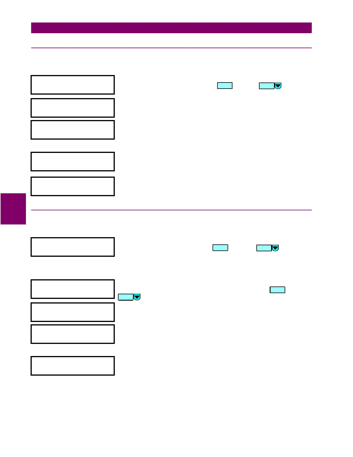
y INST DIFFERENTIAL
y
[ENTER] for more
This message indicates the start of the
INSTANTANEOUS DIFFERENTIAL
section.
To continue with these setpoints press , or press to go to the
next section.
INST DIFFERENTIAL
FUNCTION: Enabled
Range: Disabled / Enabled
INST DIFFERENTIAL
TARGET: Latched
Range: Self-reset / Latched / None
Select “None” to inhibit the display of the target message when the element
operates. Thus an element whose “target type” is “None” never disables the
LED self-test feature since it cannot generate a displayable target message.
INST DIFFERENTIAL
PICKUP: 8.00 x CT
Range: 3.00 to 20.00 (steps of 0.01)
Enter the level of differential current (in units of relay nominal current) above
which the instantaneous differential element will pickup and operate.
INST DIFFERENTIAL
BLOCK: Disabled
Range: Disabled / Logc Inpt 1 (2-16) /Virt Inpt 1 (2-16) / Output Rly 1 (2-8) /
SelfTest Rly / Virt Outpt 1 (2-5)
y PHASE OC
y [ENTER] for more
This message indicates the start of the
PHASE OVERCURRENT
section. To
continue with these setpoints press , or press to go to the
next section.
y W1 PHASE TIME OC
y [ENTER] for more
This message indicates the start of the
PHASE TIME OVERCURRENT
section for
Winding 1 (2/3). To continue with these setpoints press , or press
to go to the next section.
W1 PHASE TIME OC
FUNCTION: Enabled
Range: Disabled / Enabled
W1 PHASE TIME OC
TARGET: Latched
Range: Self-reset / Latched / None
Select
None
to inhibit the display of the target message when the element
operates. Thus an element whose “target type” is
None
never disables the
LED self-test feature since it cannot generate a displayable target message.
W1 PHASE TIME OC
PICKUP: 1.20 x CT
Range: 0.05 to 20.00 (steps of 0.01)
Enter the phase current level (in units of relay nominal current) above which
the W1 (2/3) phase time overcurrent element will pickup and start timing.
ENTER
MESSAGE
ENTER
MESSAGE
ENTER
MESSAGE

 Loading...


