8-16 745 Transformer Management Relay GE Power Management
8.2 MODBUS PROTOCOL 8 COMMUNICATIONS
8
c) FUNCTION CODE 06H SUBSTITUTION
Function code 06h (STORE SINGLE SETPOINT) is simply a shorter version of function code 10h (STORE
MULTIPLE SETPOINTS). Using function code 10h, such that the NUMBER OF SETPOINTS stored is 1, has
the same effect as function code 06h. The message format and example is shown below.
Request slave device 11 to write the single setpoint value 00C8 at setpoint address 1100.
8.2.18 MEMORY MAP ORGANIZATION
Data in the 745 that is accessible via computer communications is grouped into several sections of the mem-
ory map as shown in the table below. All memory map locations are two-byte (16-bit) values. The following
section lists all memory map locations. Addresses for all locations are in hexadecimal. Consult the range, step,
units, and the data format (listed after the memory map) to interpret the register values.
Master Query Message: Example (hex):
SLAVE ADDRESS 11 query message for slave 11
FUNCTION CODE 10 store multiple setpoints (substituted for code 06H)
DATA STARTING ADDRESS: high order byte 11 data starting at address 1100
DATA STARTING ADDRESS: low order byte 00
NUMBER OF SETPOINTS: high order byte 00 1 setpoint values = 2 bytes total
NUMBER OF SETPOINTS: low order byte 01
BYTE COUNT 02 2 bytes of data
DATA #1: high order byte 00 data for address 1100 = 00C8
DATA #1: low order byte C8
CRC: low order byte 6B
CRC: high order byte 07
Field: Example (hex):
SLAVE ADDRESS 11 response message from slave 11
FUNCTION CODE 00 store multiple setpoint values
DATA STARTING ADDRESS: high order byte 11 data starting at address 1100
DATA STARTING ADDRESS: low order byte 00
NUMBER OF SETPOINTS: high order byte 00 1 setpoint values = 2 bytes total
NUMBER OF SETPOINTS: low order byte 01
CRC: low order byte 06
CRC: high order byte 65
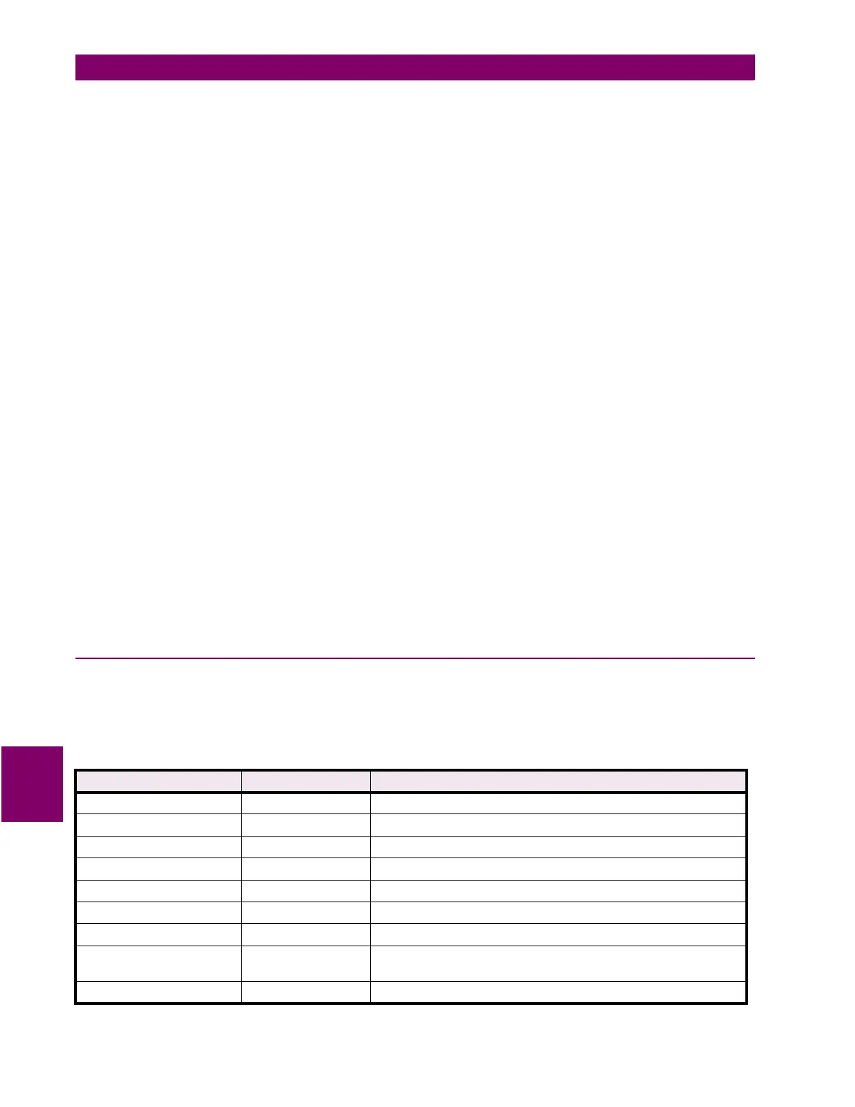
Table 8–5: MEMORY MAP ORGANIZATION
MEMORY MAP SECTION ADDRESS RANGE DESCRIPTION
Product ID 0000 to 007F Identification and revision information. Read only.
Commands 0080 to 00FF Substitute command locations. Read and write.
User Map 0100 to 01FF User Map Values and Addresses. Read and write.
Actual Values 0200 to 07FF Read only.
Event Recorder 0800 to 0FFF Read only (except "Event Record Selector Index").
Common Setpoints 1000 to 1FFF Read and write.
Setpoint Group 1/2/3/4 2000 to 3FFF Read and write.
Trace Memory 4000 to 47FF Read only (except "Trace Buffer Selector Index" and "Trace
Channel Selector Index").
Playback Memory 4800 to 4FFF Read and write.

 Loading...


