GE Power Management 745 Transformer Management Relay 6-3
6 ACTUAL VALUES 6.2 A1 STATUS
6
6.2.5 OUTPUT RELAYS
6.2.6 VIRTUAL OUTPUTS
6.2.7 SELF-TEST ERRORS
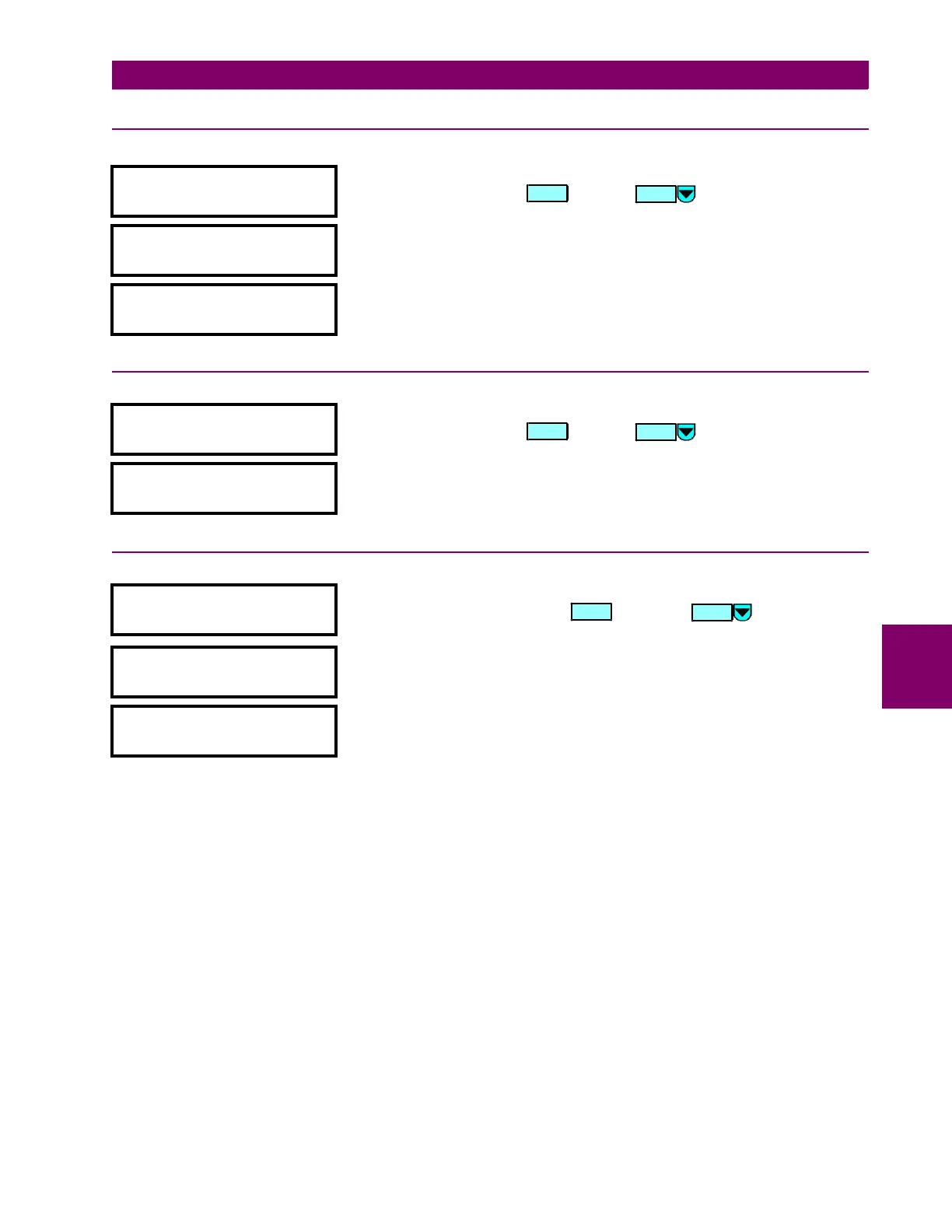
y OUTPUT RELAYS
y [ENTER] for more
This message indicates the start of the Output Relays actual values. To view
these actual values press or press for the next section.
OUTPUT RELAY 1
STATE: De-energized
This message displays the state of output relay #1. Similar messages
appear sequentially for output relays 2 through 8.
SELF-TEST RELAY
STATE: Energized
This message displays the state of the self-test relay.
y VIRTUAL OUTPUTS
y [ENTER] for more
This message indicates the start of the Virtual Outputs actual values. To view
these actual values press or press for the next section.
VIRTUAL OUTPUT 1
STATE: De-energized
This message displays the state of virtual output #1. Similar messages
appear sequentially for virtual outputs 2 through 5.
y SELF-TEST ERRORS
y [ENTER] for more
This message indicates the start of the Self-Test Errors actual values. To
view these actual values press . Pressing proceeds to the
ending of page S1.
FLEXLOGIC EQN ERROR:
None
This message displays the source of the error occurring in the FlexLogic™
equation.
BAD SETTINGS ERROR:
None
This message displays the cause of a bad setting made within the setting of
the setpoints.
ENTER
MESSAGE
ENTER
MESSAGE
ENTER
MESSAGE

 Loading...


