GE Power Management 745 Transformer Management Relay 8-5
8 COMMUNICATIONS 8.2 MODBUS PROTOCOL
8
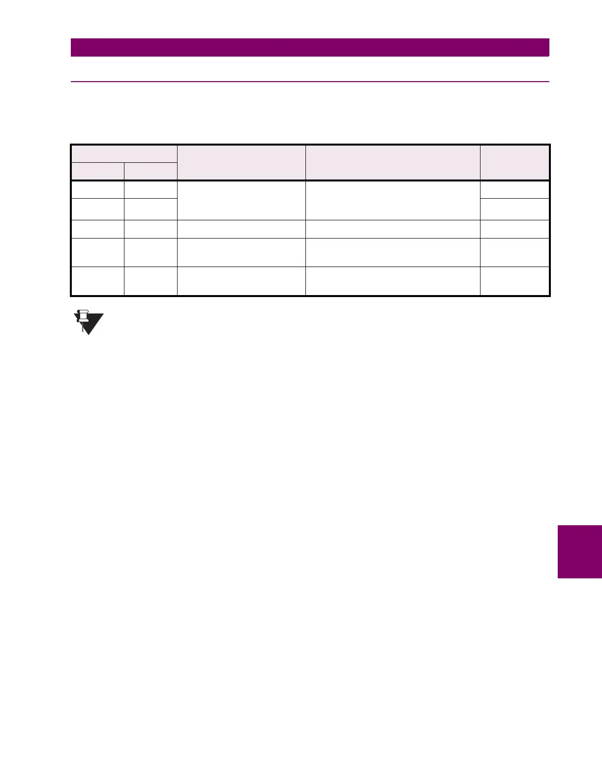
8.2.8 SUPPORTED FUNCTION CODES
The second byte of every message is the function code. Modbus defines function codes of 01h to 7Fh. The GE
Power Management SR Series Modbus protocol supports some of these functions, as summarized below.
* Since some programmable logic controllers only support function codes 03h (or 04h) and 10h, most
of the above Modbus commands can be performed by reading from or writing to special addresses in
the 745 memory map using these function codes. See section entitled FUNCTION CODE SUBSTI-
TUTIONS for details.
Table 8–1: GE POWER MANAGEMENT FUNCTION CODES
FUNCTION CODE DEFINITION DESCRIPTION SUBSTITUTE
HEX DEC
03 3 READ ACTUAL VALUES
OR SETPOINTS
Read actual value or setpoint registers
from one or more consecutive memory
map register addresses.
04H
04 4 03H
05 5 EXECUTE OPERATION Perform 745 specific operations. 10H
06 6 STORE SINGLE
SETPOINT
Write a specific value into a single
setpoint register.
10H
10 16 STORE MULTIPLE
SETPOINTS
Write specific values into one or more
consecutive setpoint registers.
---
NOTE

 Loading...


