5-60 745 Transformer Management Relay GE Power Management
5.6 S4 ELEMENTS 5 SETPOINTS
5
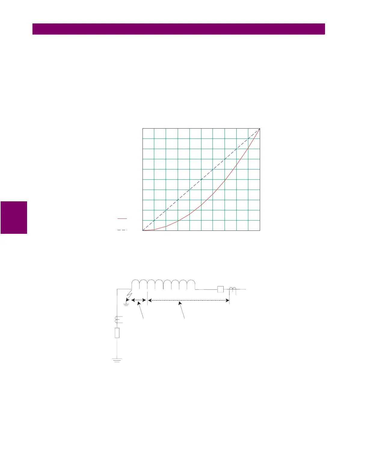
An internal ground fault on an impedance grounded wye winding (see Figure 5–10: RESISTANCE
GROUNDED WYE WINDING above) produces a fault current (I
F
) dependent on the value of the ground
impedance and the position of the fault on the winding with respect to the neutral point. The resultant primary
current (I
P
) will be negligible for faults on the lower 30% of the winding since the fault voltage will not be the
system voltage but the result of the transformation ratio between the primary windings and the percentage of
shorted turns on the secondary. Therefore, the resultant differential currents could be below the slope thresh-
old of the percent differential element and thus the fault could go undetected. The graph below shows the rela-
tionship between the primary (I
P
) and fault (I
F
) currents as a function of the distance of the fault point from the
neutral and Figure 5–12: RGF AND PERCENT DIFFERENTIAL ZONES OF PROTECTION outlines the zones
of effective protection along the winding for an impedance grounded wye.
Figure 5–11: FAULT CURRENTS VS. FAULT POINT FROM NEUTRAL
Figure 5–12: RGF AND PERCENT DIFFERENTIAL ZONES OF PROTECTION
The 745 implementation of RGF (Figure 5–13: RESTRICTED GROUND FAULT IMPLEMENTATION) is a low
impedance current differential scheme where "spill" current due to CT tolerances is handled via load bias simi-
lar to the percent differential. The 745 calculates the vectorial difference of the residual and ground currents
(i.e. 3
I
0
-
I
g
) and divides this by the maximum line current (
I
max
) to produce a percent slope value. The slope
setting allows the user to determine the sensitivity of the element based on the class and quality of the CTs
used. Typically no more than 4% overall error due to CT "spill" is assumed for protection class CTs at nominal
load.
0 10 20 30 40 50 60 70 80 90 100
0
10
20
30
40
50
60
70
80
90
100
Ip(x)
Ifault(x)
% Max Ifault
Ifault
Ip
x = distance of fault from neutral
Rg
35%
RGF
ZONE
DIFFERENTIAL
ZONE
WINDING

 Loading...


