GE Power Management 745 Transformer Management Relay 5-81
5 SETPOINTS 5.7 S5 OUTPUTS
5
As mentioned above, the parameters of an equation can contain either INPUTS or GATES.
Inputs and gates are combined into a FlexLogic™ equation. The sequence of entries in the linear array of
parameters follows the general rules listed in the following section.
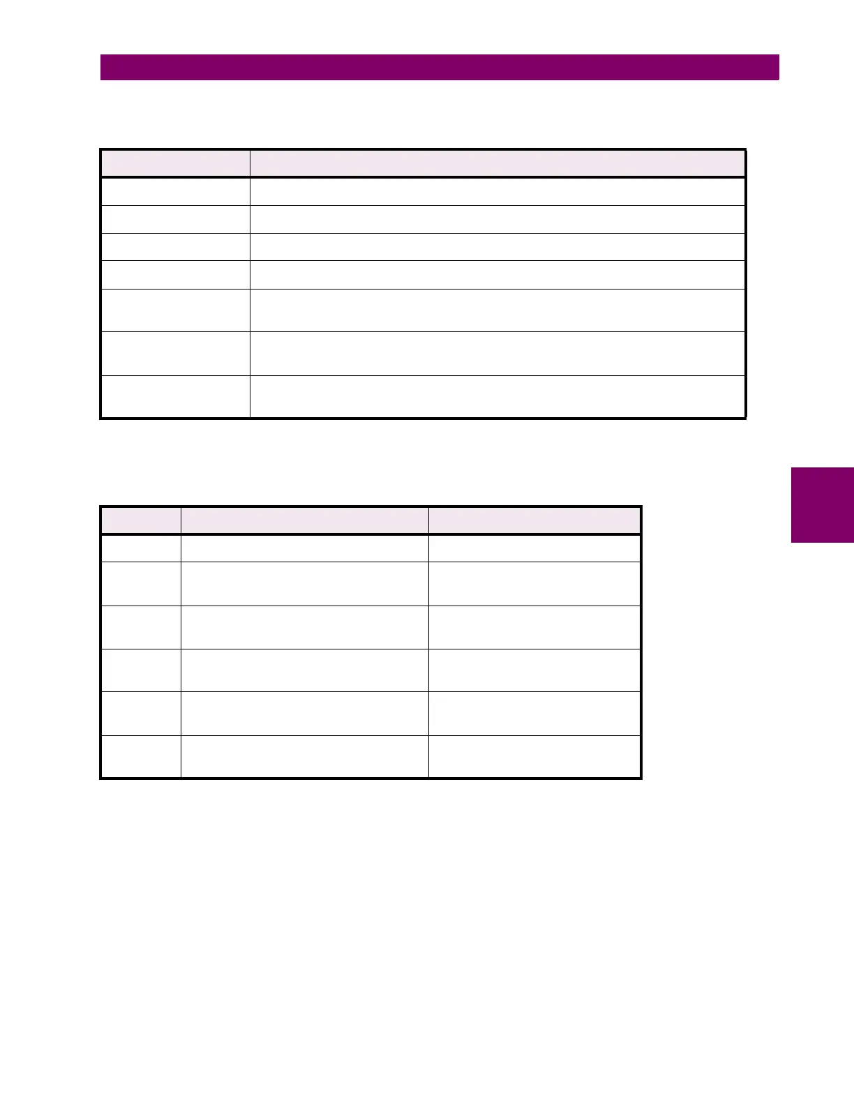
Table 5–6: FLEXLOGIC™ INPUT TYPES
INPUTS INPUT IS “1” (= ON) IF...
element* pickup the pickup setting of the element is exceeded
element* operate the pickup setting of the element is exceeded for the programmed time delay
logic inputs 1 to 16 the logic input contact is asserted
virtual inputs 1 to 16 the virtual input is asserted
output relays 1 to 8 the output relay operates
(i.e. evaluation of the FlexLogic™ equation results in a ‘1’)
virtual outputs 1 to 5 the virtual output operates
(i.e. evaluation of the FlexLogic™ equation results in a ‘1’)
timers 1 to 10 the timer runs to completion
(i.e. the ‘start’ condition is met for the programmed time delay)
* element refers to any protection or monitoring element programmed under page
S4 ELEMENTS
Table 5–7: FLEXLOGIC™ GATES
GATES NUMBER OF INPUTS OUPUT IS “1” (= ON) IF...
NOT 1 input is ‘0’
OR 2 to 19 (for 20 parameter equations)
2 to 9 (for 10 parameter equations)
any input is ‘1’
AND 2 to 19 (for 20 parameter equations)
2 to 9 (for 10 parameter equations)
all inputs are ‘1’
NOR 2 to 19 (for 20 parameter equations)
2 to 9 (for 10 parameter equations)
all inputs are ‘0’
NAND 2 to 19 (for 20 parameter equations)
2 to 9 (for 10 parameter equations)
any input is ‘0’
XOR 2 to 19 (for 20 parameter equations)
2 to 9 (for 10 parameter equations)
odd number of inputs are ‘1’

 Loading...


