8-18 745 Transformer Management Relay GE Power Management
8.3 MODBUS MEMORY MAP 8 COMMUNICATIONS
8
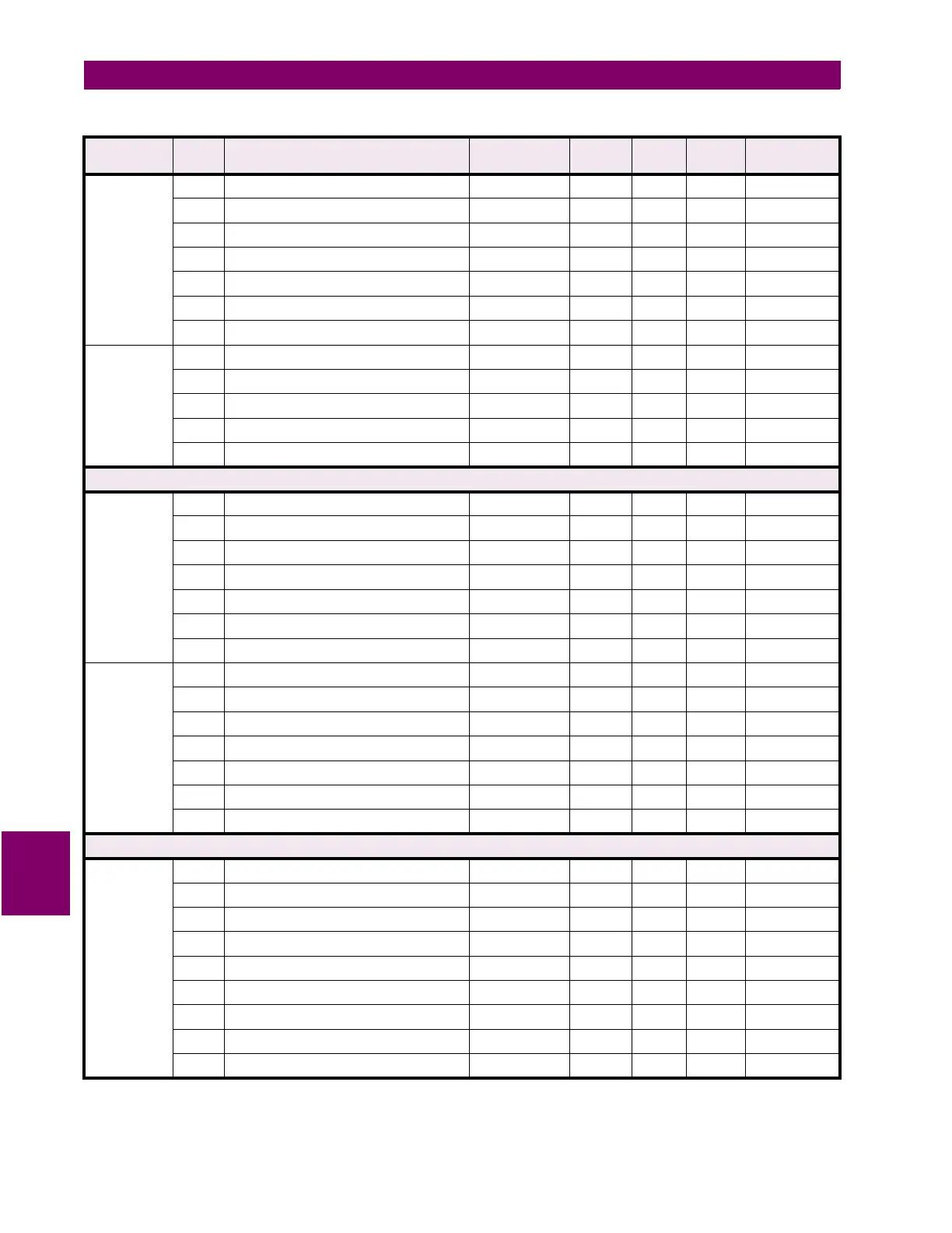
VIRTUAL
INPUTS
continued
009C Virtual Input 13 Programmed State --- --- --- F43 0
009D Virtual Input 14 Programmed State --- --- --- F43 0
009E Virtual Input 15 Programmed State --- --- --- F43 0
009F Virtual Input 16 Programmed State --- --- --- F43 0
00A0 Reserved
↓↓ ↓
↓↓↓ ↓
00EF Reserved
TIME/DATE 00F0 Time (2 registers) --- --- --- F22 ---
00F2 Date (2 registers) --- --- --- F23 ---
00F4 Reserved
↓↓ ↓
↓↓↓ ↓
00FF Reserved
User Map (Addresses 0100 to 01FF) - Read / Write
USER MAP
VALUES
0100 User Map Value #1 --- --- --- --- ---
0101 User Map Value #2 --- --- --- --- ---
↓↓ ↓
↓↓↓ ↓
0177 User Map Value #120 --- --- --- --- ---
0178 Reserved
↓↓ ↓
↓↓↓ ↓
017F Reserved
USER MAP
ADDRESSES
0180 User Map Address #1 0000 to FFFF 0001 hex F1 0000 hex
0181 User Map Address #2 0000 to FFFF 0001 hex F1 0000 hex
↓↓ ↓
↓↓↓ ↓
01F7 User Map Address #120 0000 to FFFF 0001 hex F1 0000 hex
01F8 Reserved
↓↓ ↓
↓↓↓ ↓
01FF Reserved
Actual Values (Addresses 0200 to 07FF) - Read Only
SYSTEM
STATUS
0200 Relay Status --- --- --- F20 ---
0201 System Status --- --- --- F21 ---
0202 Conditions --- --- --- F35 ---
0203 Operation Status --- --- --- F44 ---
0204 Logic Input Status --- --- --- F49 ---
0205 Output Relay Status --- --- --- F50 ---
0206 Reserved
↓↓ ↓
↓↓↓ ↓
0207 Reserved
Table 8–6: 745 MEMORY MAP (Sheet 2 of 57)
GROUP ADDR
(HEX)
DESCRIPTION RANGE STEP
VALUE
UNITS FORMAT
CODE
FACTORY
DEFAULT

 Loading...


