8-50 745 Transformer Management Relay GE Power Management
8.3 MODBUS MEMORY MAP 8 COMMUNICATIONS
8
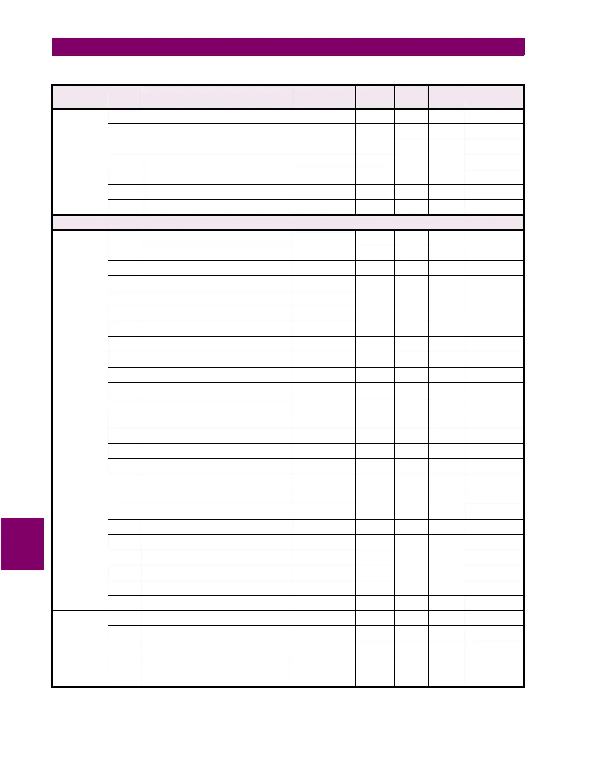
SIMULATION
FAULT VALUES
continued
1E47 Fault Winding 3 Ground Current Angle 0 to 359 1 ° Lag F1 0° Lag
1E48 Fault Voltage Input Magnitude 0.0 to 2.0 0.1
×
VT F2 10 = 1.0
×
VT
1E49 Fault Voltage Input Angle 0 to 359 1 ° Lag F1 0° Lag
1E4A Fault Frequency 45.00 to 60.00 0.01 Hz F3 60.00 Hz
1E4B Reserved
↓↓ ↓
↓↓↓ ↓
1FFF Reserved
Setpoint Group 1/2/3/4 (Addresses 2000 to 3FFF) - Read / Write
PERCENT
DIFFERENTIAL
2000 Percent Differential Function --- --- --- F30 1 = Enabled
2001 Percent Differential Target --- --- --- F46 1 = Latched
2002 Percent Differential Pickup 0.05 to 1.00 0.01
×
CT F3 30 = 0.30
×
CT
2003 Percent Differential Slope 1 15 to 100 1 % F1 25%
2004 Percent Differential Break Point 1.0 to 20.0 0.1
×
CT F2 20 = 2.0
×
CT
2005 Percent Differential Slope 2 50 to 200 1 % F1 100%
2006 Percent Differential Block --- --- --- F87 0 = Disabled
2007 Reserved
HARMONIC
INHIBIT
2008 Harmonic Inhibit Function --- --- --- F30 1 = Enabled
2009 Harmonic Inhibit Parameters --- --- --- F64 0 = 2nd
200A Harmonic Averaging --- --- --- F30 0 = Disabled
200B Harmonic Inhibit Level 0.1 to 65.0 0.1 % ƒo F2
200 = 20.0% ƒ
o
200C Reserved
ENERGIZATION
INHIBIT
200D Energization Inhibit Function --- --- --- F30 1 = Enabled
200E Energization Inhibit Parameters --- --- --- F64 0 = 2nd
200F Harmonic Averaging --- --- --- F30 1 = Enabled
2010 Energization Inhibit Level 0.1 to 65.0 0.1 % ƒo F2
200 = 20.0% ƒ
o
2011 Energization Inhibit Duration 0.05 to 600.00 0.01 s F1 10 = 0.10 s
2012 Energization Sensing By Current --- --- --- F30 1 = Enabled
2013 Minimum Energization Current 0.10 to 0.50 0.01
×
CT F3 10 = 0.10
×
CT
2014 Energization Sensing By Voltage --- --- --- F30 0 = Disabled
2015 Minimum Energization Voltage 0.50 to 0.99 0.01
×
VT F3 85 = 0.85
×
VT
2016 Breakers Are Open Signal --- --- --- F88 0 = Disabled
2017 Parallel Transformer Breaker Close Signal --- --- --- F88 0 = Disabled
2018 Reserved
5TH
HARMONIC
INHIBIT
2019 5th Harmonic Inhibit Function --- --- --- F30 0 = Disabled
201A Harmonic Averaging --- --- --- F30 0 = Disabled
201B 5th Harmonic Inhibit Level 0.1 to 65.0 0.1 % ƒo F2
100 = 10.0% ƒ
o
201C Reserved
↓↓ ↓
↓↓↓ ↓
Table 8–6: 745 MEMORY MAP (Sheet 34 of 57)
GROUP ADDR
(HEX)
DESCRIPTION RANGE STEP
VALUE
UNITS FORMAT
CODE
FACTORY
DEFAULT
 Loading...


