8-82 745 Transformer Management Relay GE Power Management
8.3 MODBUS MEMORY MAP 8 COMMUNICATIONS
8
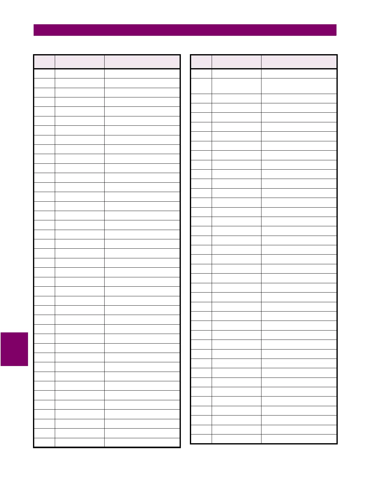
0001 1110 30 = Winding 1 Ground Inst O/C 2
0001 1111 31 = Winding 2 Ground Inst O/C 2
0010 0000 32 = Winding 3 Ground Inst O/C 2
0010 0001
33=Winding 1 Restricted Ground Fault
0010 0010
34=Winding 2 Restricted Ground Fault
0010 0011
35=Winding 3 Restricted Ground Fault
0010 0100
36=Winding 1 Restricted Ground Trend
0010 0101
37=Winding 2 Restricted Ground Trend
0010 0110
38=Winding 3 Restricted Ground Trend
0010 0111
39 = Winding 1 Neg. Seq. Time O/C
0010 1000
40 = Winding 2 Neg. Seq. Time O/C
0010 1001
41 = Winding 3 Neg. Seq. Time O/C
0010 1010 42 = Winding 1 Neg. Seq. Inst O/C
0010 1011 43 = Winding 2 Neg. Seq. Inst O/C
0010 1100 44 = Winding 3 Neg. Seq. Inst O/C
0010 1101 45 = Underfrequency 1
0010 1110 46 = Underfrequency 2
0010 1111 47 = Frequency Decay Rate 1
0011 0000 48 = Frequency Decay Rate 2
0011 0001 49 = Frequency Decay Rate 3
0011 0010 50 = Frequency Decay Rate 4
0011 0011 51 = Overfrequency
0011 0100 52 = 5th Harmonic Level
0011 0101 53 = Volts-Per-Hertz 1
0011 0110 54 = Volts-Per-Hertz 2
0011 0111 55 = Winding 1 THD Level
0011 1000 56 = Winding 2 THD Level
0011 1001 57 = Winding 3 THD Level
0011 1010 58 = Winding 1 Harmonic Derating
0011 1011 59 = Winding 2 Harmonic Derating
0011 1100 60 = Winding 3 Harmonic Derating
0011 1101
61 = Hottest-Spot Temperature Limit
0011 1110 62 = Loss-Of-Life Limit
0011 1111 63 = Analog Input Level 1
0100 0000 64 = Analog Input Level 2
0100 0001 65 = Winding 1 Current Demand
0100 0010 66 = Winding 2 Current Demand
0100 0011 67 = Winding 3 Current Demand
0100 0100 68 = Transformer Overload
0100 0101 69 = Aging Factor Limit
Table 8–7: 745 DATA FORMATS (Sheet 17 of 35)
FORMAT
CODE
APPLICABLE BITS DEFINITION
0100 0110 70 = Tap Changer Failure
0000 1010 xxxx xxxx Token = Element Operated
(data same as for Element Pickup)
0000 1011 xxxx xxxx Token = Logic Input Asserted
0000 0000 0 = Logic Input 1
0000 0001 1 = Logic Input 2
0000 0010 2 = Logic Input 3
0000 0011 3 = Logic Input 4
0000 0100 4 = Logic Input 5
0000 0101 5 = Logic Input 6
0000 0110 6 = Logic Input 7
0000 0111 7 = Logic Input 8
0000 1000 8 = Logic Input 9
0000 1001 9 = Logic Input 10
0000 1010 10 = Logic Input 11
0000 1011 11 = Logic Input 12
0000 1100 12 = Logic Input 13
0000 1101 13 = Logic Input 14
0000 1110 14 = Logic Input 15
0000 1111 15 = Logic Input 16
0000 1100 xxxx xxxx Token = Virtual Input Asserted
0000 0000 0 = Virtual Input 1
0000 0001 1 = Virtual Input 2
0000 0010 2 = Virtual Input 3
0000 0011 3 = Virtual Input 4
0000 0100 4 = Virtual Input 5
0000 0101 5 = Virtual Input 6
0000 0110 6 = Virtual Input 7
0000 0111 7 = Virtual Input 8
0000 1000 8 = Virtual Input 9
0000 1001 9 = Virtual Input 10
0000 1010 10 = Virtual Input 11
0000 1011 11 = Virtual Input 12
0000 1100 12 = Virtual Input 13
0000 1101 13 = Virtual Input 14
0000 1110 14 = Virtual Input 15
0000 1111 15 = Virtual Input 16
0000 1101 xxxx xxxx Token = Output Relay Operated
0000 0000 0 = Output Relay 1
0000 0001 1 = Output Relay 2
Table 8–7: 745 DATA FORMATS (Sheet 18 of 35)
FORMAT
CODE
APPLICABLE BITS DEFINITION
 Loading...


