8-88 745 Transformer Management Relay GE Power Management
8.3 MODBUS MEMORY MAP 8 COMMUNICATIONS
8
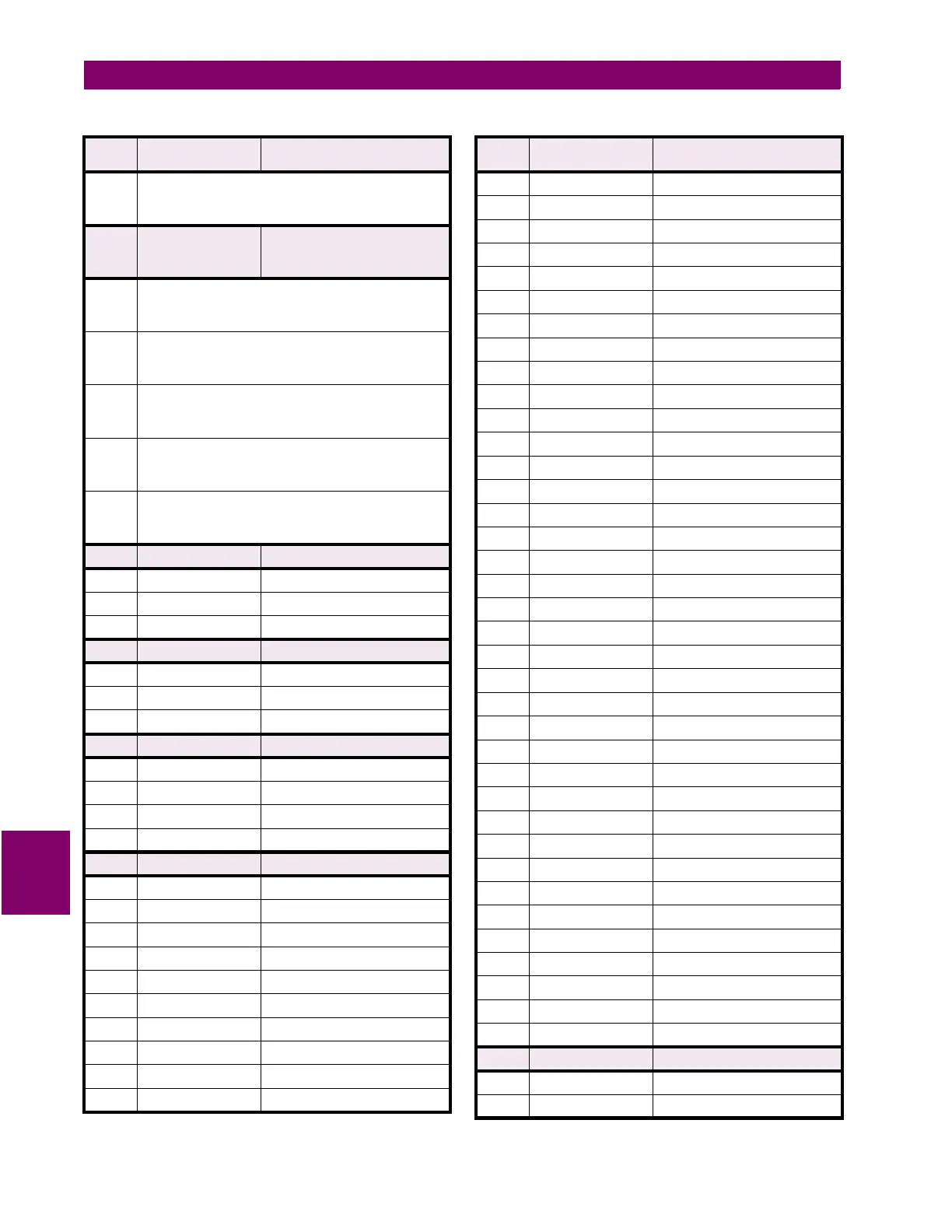
For CT PRIMARY > 2000 A
Format: Unsigned value, scaled by 10
Example: 12340 stored as 1234
F83 16 bits UNSIGNED VALUE
AUTORANGING BASED ON
WINDING 3 GROUND CT PRIMARY
For CT PRIMARY
≤
2 A
Format: Unsigned value, 3 decimal places
Example: 1.234 stored as 1234
For 2 A < CT PRIMARY
≤
20 A
Format: Unsigned value, 2 decimal places
Example: 12.34 stored as 1234
For 20 A < CT PRIMARY
≤
200 A
Format: Unsigned value, 1 decimal place
Example: 123.4 stored as 1234
For 200 A < CT PRIMARY
≤
2000 A
Format: Unsigned value
Example: 1234 stored as 1234
For CT PRIMARY > 2000 A
Format: Unsigned value, scaled by 10
Example: 12340 stored as 1234
F84 16 bits IRIG-B SIGNAL TYPE
0000 0000 0000 0000 0 = None
0000 0000 0000 0001 1 = DC Shift
0000 0000 0000 0010 2 = Amplitude Modulated
F85 16 bits TRACE MEMORY TRIGGER CAUSE
0000 0000 0000 0000 0 = No Trigger
0000 0000 0000 0001 1 = Manual Trigger
0000 0000 0000 0010 2 = Automatic Trigger
F86 16 bits VOLTS-PER-HERTZ CURVE SHAPES
0000 0000 0000 0000 0 = Definite Time
0000 0000 0000 0001 1 = Inv Curve 1
0000 0000 0000 0010 2 = Inv Curve 2
0000 0000 0000 0011 3 = Inv Curve 3
F87 16 bits BLOCK SIGNAL
0000 0000 0000 0000 0 = Disabled
0000 0000 0000 0001 1 = Logic Input 1
0000 0000 0000 0010 2 = Logic Input 2
0000 0000 0000 0011 3 = Logic Input 3
0000 0000 0000 0100 4 = Logic Input 4
0000 0000 0000 0101 5 = Logic Input 5
0000 0000 0000 0110 6 = Logic Input 6
0000 0000 0000 0111 7 = Logic Input 7
0000 0000 0000 1000 8 = Logic Input 8
0000 0000 0000 1001 9 = Logic Input 9
Table 8–7: 745 DATA FORMATS (Sheet 29 of 35)
FORMAT
CODE
APPLICABLE BITS DEFINITION
0000 0000 0000 1010 10 = Logic Input 10
0000 0000 0000 1011 11 = Logic Input 11
0000 0000 0000 1100 12 = Logic Input 12
0000 0000 0000 1101 13 = Logic Input 13
0000 0000 0000 1110 14 = Logic Input 14
0000 0000 0000 1111 15 = Logic Input 15
0000 0000 0001 0000 16 = Logic Input 16
0000 0000 0001 0001 17 = Virtual Input 1
0000 0000 0001 0010 18 = Virtual Input 2
0000 0000 0001 0011 19 = Virtual Input 3
0000 0000 0001 0100 20 = Virtual Input 4
0000 0000 0001 0101 21 = Virtual Input 5
0000 0000 0001 0110 22 = Virtual Input 6
0000 0000 0001 0111 23 = Virtual Input 7
0000 0000 0001 1000 24 = Virtual Input 8
0000 0000 0001 1001 25 = Virtual Input 9
0000 0000 0001 1010 26 = Virtual Input 10
0000 0000 0001 1011 27 = Virtual Input 11
0000 0000 0001 1100 28 = Virtual Input 12
0000 0000 0001 1101 29 = Virtual Input 13
0000 0000 0001 1110 30 = Virtual Input 14
0000 0000 0001 1111 31 = Virtual Input 15
0000 0000 0010 0000 32 = Virtual Input 16
0000 0000 0010 0001 33 = Output Relay 1
0000 0000 0010 0010 34 = Output Relay 2
0000 0000 0010 0011 35 = Output Relay 3
0000 0000 0010 0100 36 = Output Relay 4
0000 0000 0010 0101 37 = Output Relay 5
0000 0000 0010 0110 38 = Output Relay 6
0000 0000 0010 0111 39 = Output Relay 7
0000 0000 0010 1000 40 = Output Relay 8
0000 0000 0010 1001 41 = Self-Test Relay
0000 0000 0010 1010 42 = Virtual Output 1
0000 0000 0010 1011 43 = Virtual Output 2
0000 0000 0010 1100 44 = Virtual Output 3
0000 0000 0010 1101 45 = Virtual Output 4
0000 0000 0010 1110 46 = Virtual Output 5
F88 16 bits ASSERT SIGNAL
0000 0000 0000 0000 0 = Disabled
0000 0000 0000 0001 1 = Logic Input 1
Table 8–7: 745 DATA FORMATS (Sheet 30 of 35)
FORMAT
CODE
APPLICABLE BITS DEFINITION

 Loading...


