GE Power Management 745 Transformer Management Relay 5-47
5 SETPOINTS 5.6 S4 ELEMENTS
5
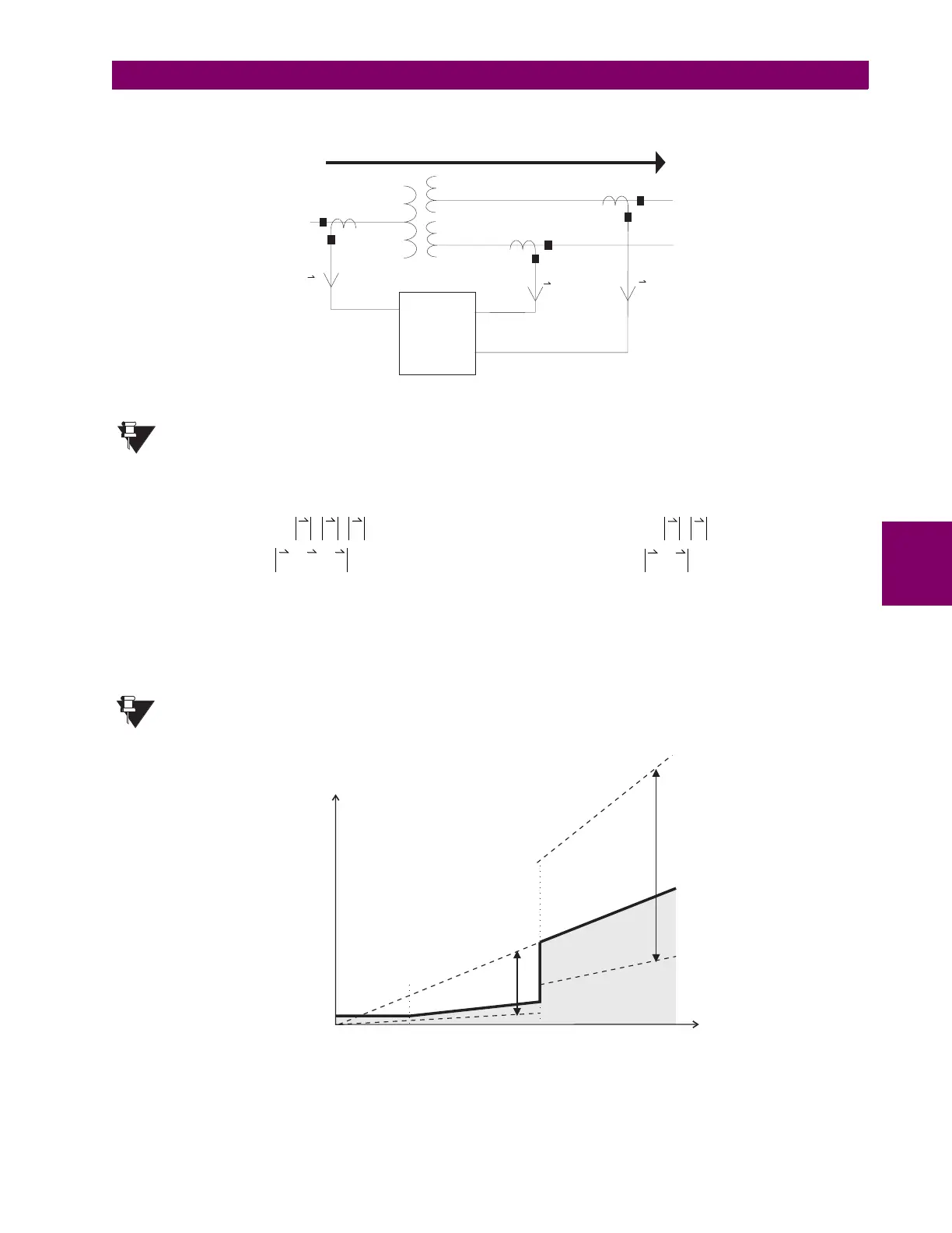
The basic operating principle of the percent differential element can be described by the following diagram and
its associated equations:
Figure 5–6: PERCENT DIFFERENTIAL OPERATING PRINCIPLE
Restraint current calculations have been changed from
average
to
maximum
to provide better
security during external faults.
where
I
restraint
= per-phase
maximum
of the currents after phase, ratio, and zero-sequence correction
I
differential
= per-phase
vector sum
of currents after phase, ratio, and zero-sequence correction
In the above equations, the 180° phase shift due to the wiring connections is taken into account, hence
the + sign to obtain the differential current.
Figure 5–7: PERCENT DIFFERENTIAL – DUAL SLOPE CHARACTERISTIC
Basic Operating Principle (3-winding): Basic Operating Principle (2-winding):
Percent
Diff
Element
CT1
CT2
CT3
V1
V2
V3
I
1
I
2
I
3
NOTE
I
r
I
restraint
max
I
1
I
2
I
3
,,()
==
I
d
I
differential
I
1
I
2
I
3
++==
%slope
I
d
I
r
---- 100%
×
=
I
r
I
restraint
max
I
1
I
2
,()
==
I
d
I
differential
I
1
I
2
+==
%slope
I
d
I
r
----
100%
×
=
NOTE
100%
OPERATE
REGION
RESTRAINT
REGION
SLOPE 1
25%
SLOPE 2
100%
200%
50%
I (x CT)
restraint
I (x CT)
differential
15%
0.05
1.00
PICKUP 0.30
2.0
KNEEPOINT
 Loading...


