NetworX Version 3 Installation Manual
12
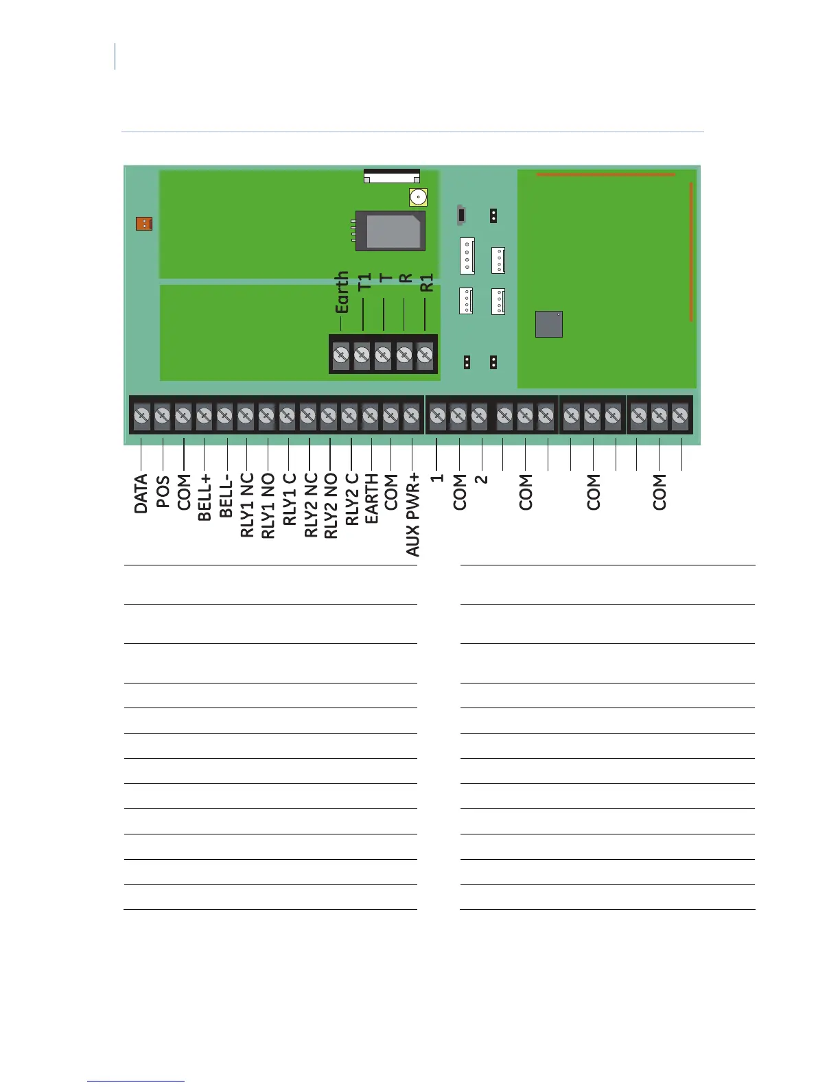
Figure 2. NetworX V3 inputs and outputs
4
3
5
6
7
8
DATA
Connect to Data terminal of keypad
and expanders
COM Power (−)
POS (+)
Connect to Positive (+) terminal of
keypad and expanders
AUX PWR+ Power (+)
COM
Connect to negative (−) terminal of
keypad and expanders
AUX PWR+ Power (+)
BELL+ Internal bell positive
1 Zone 1 [1]
BELL− Internal bell negative
COM Common (−) for zone 1 and zone 2 [1]
AUX PWR+ Power (+)
2 Zone 2 [1]
Relay 1 NC Relay 1 (normally closed)
3 to 8, COM Zones 3 to 8 and common terminals [1]
Relay 1 NO Relay 1 (normally open)
Earth Ground
Relay 1 C Relay 1 (common)
T1 House Telephone Tip
Relay 2 NC Relay 2 (normally closed)
T Telephone Tip
Relay 2 NO Relay 2 (normally open)
R Telephone Ring
Relay 2 C Relay 2 (common)
R1 House Telephone Ring
[1] The number of onboard zones differs for particular panel models. Refer to “NetworX V3 technical
specifications” on page 13.

 Loading...