NetworX Version 3 Installation Manual
11
Chapter A1 Introducing the NetworX V3
system
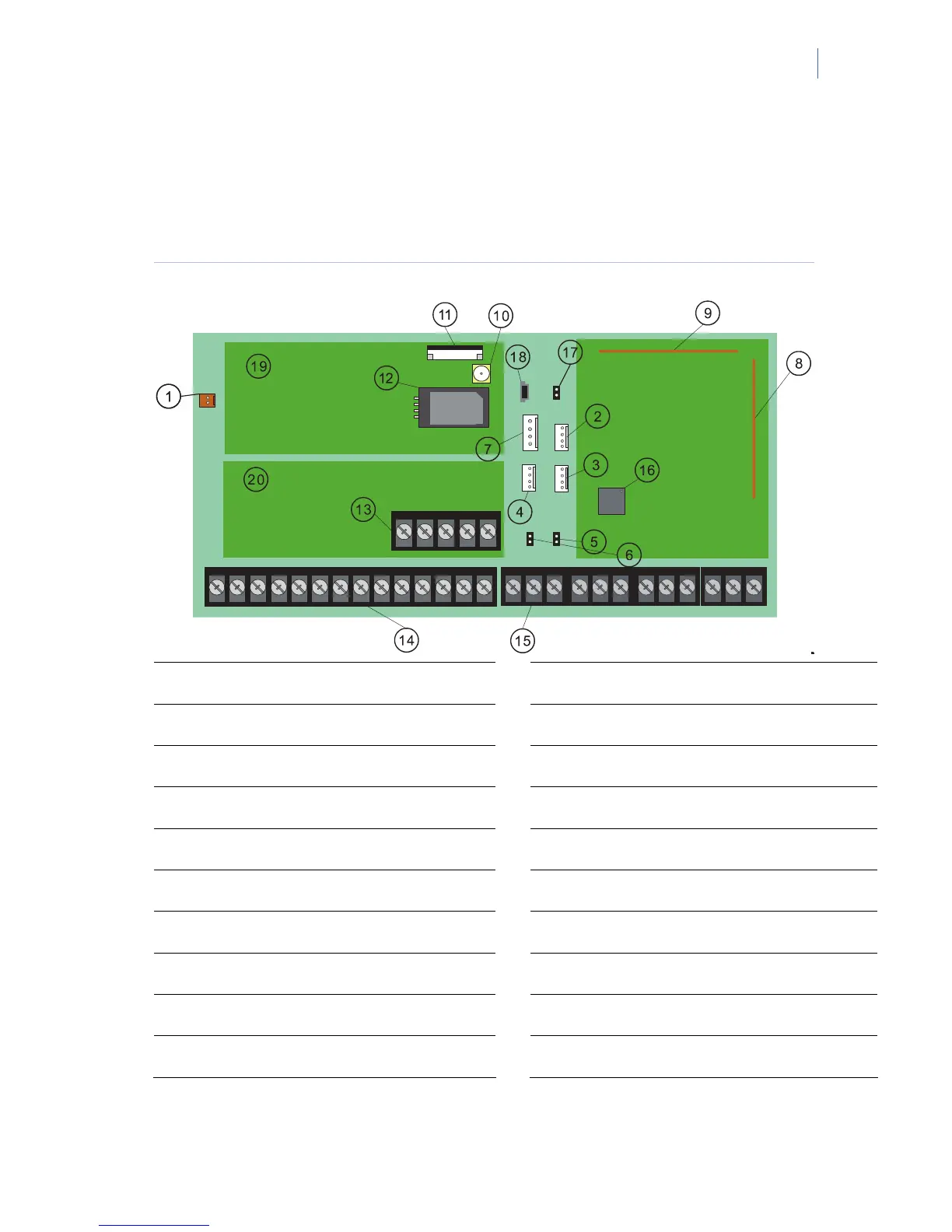
NetworX V3 diagram
Figure 1. NetworX V3 board diagram
1
Transformer
B
VVMIQ Connector
2
NetworX Bus (internal)
C
SIM Card Holder
3
NetworX Bus (internal)
D
Telephone connections (see
Figure 2)
4 NetworX Bus (internal)
E
Outputs (see
Figure 2)
5
Box Tamper
F
Inputs (see
Figure 2) [1]
6
Box Tamper
G
RF microprocessor
7
Audio Tap Outputs
H
Flash/DL900 jumper
8
Antenna
I
Mini USB connection
9
Antenna
J
GSM Modem (for status LEDs description,
see page
194)
A
GSM Antenna Connector
K
PSTN Modem
[1] The number of onboard zones differs for particular panel models. Refer to “NetworX V3 technical
specifications”
on page 13.

 Loading...