GE H
EALTHCARE
D
IRECTION
GA091568, R
EVISION
5 VIVID E9 S
ERVICE
M
ANUAL
Chapter 8 - Replacement procedures 8 - 161
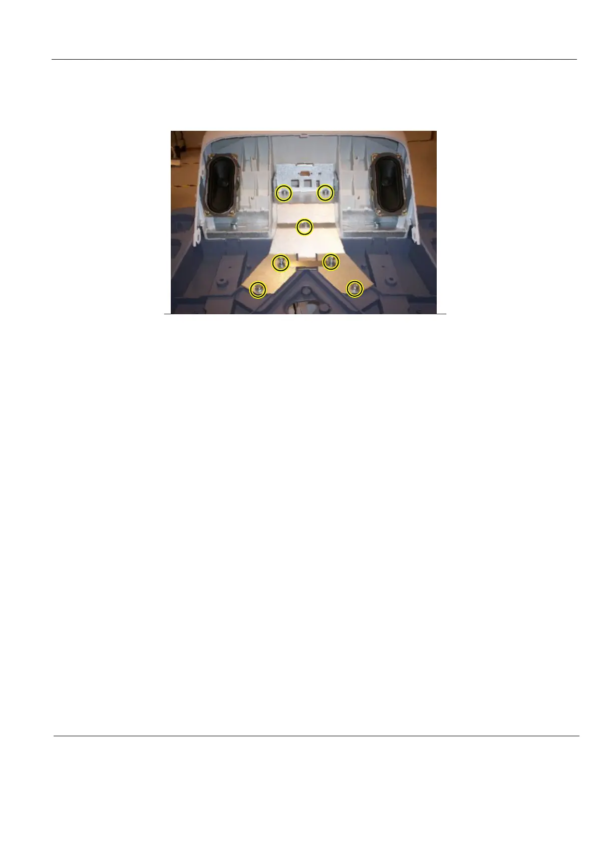
8-6-29-2 Remove the Bulkhead Plate
The Bulkhead Plate is used to secure the Upper UI Frame to the Lower UI Frame.
1.) Remove the seven fixing screws (see: Figure 8-170 "The Bulkhead Plate" on page 8-161).
2.) Remove the Bulkhead Plate and the Cable Clamp.
8-6-29-3 Install the Bulkhead Plate
1.) Position the Bulkhead Plate so it aligns with the holes for the fixing screws.
2.) Install the seven fixing screws as described below:
- The two upper screws are M6 x 20, Torque: 8.5 Nm.
- The next screw is M6 x 45, Torque: 8.5 Nm.
- The lower left-most screw is M6 x 30, Torque: 8.5 Nm.
- The three other lower screws are M6 x 25, Torque: 8.5 Nm. Two of the screws are also fixing
the Cable Clamp (see: Figure 8-170 "The Bulkhead Plate" on page 8-161).
3.) Install the Operator Panel, Lower.
4.) Install the Bulkhead Board.
5.) Install the two Speaker assemblies.
6.) Install the Operator Panel, Upper.
7.) Install the Operator Panel Knobs.
Figure 8-170 The Bulkhead Plate