GE DRAFT VOLUSON™ P8/VOLUSON™P6
DIRECTION 5775469, R
EVISION 3 DRAFT (JULY 19, 2018) BASIC SERVICE MANUAL
Chapter 4 - Functional Checks 4-5
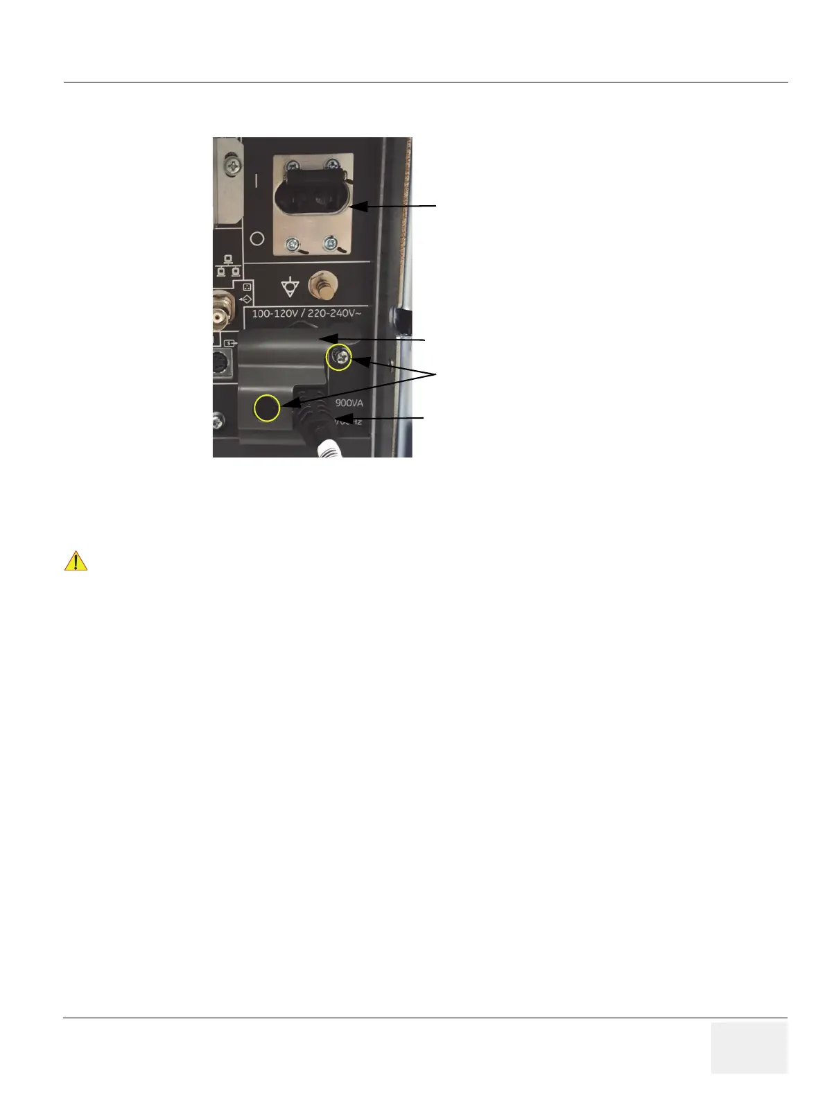
5.) After complete power down, unscrew the 2 screws and remove the pull-out protection to disconnect
the main power cable from the system or unplug it from the AC wall outlet socket.
6.) Press on the brakes to block the front caster wheels.
7.) Disconnect probes.
Figure 4-4 Circuit Breaker, pull-out protection and main power cable at rear of system
!! CAUTION:
DO NOT disconnect a probe while running (Live Scan “Write” mode)!
A software error may occur. In this case switch the unit OFF (perform a reset).
Pull-out Protection
Circuit breaker
Main power cable
2 screws

 Loading...


