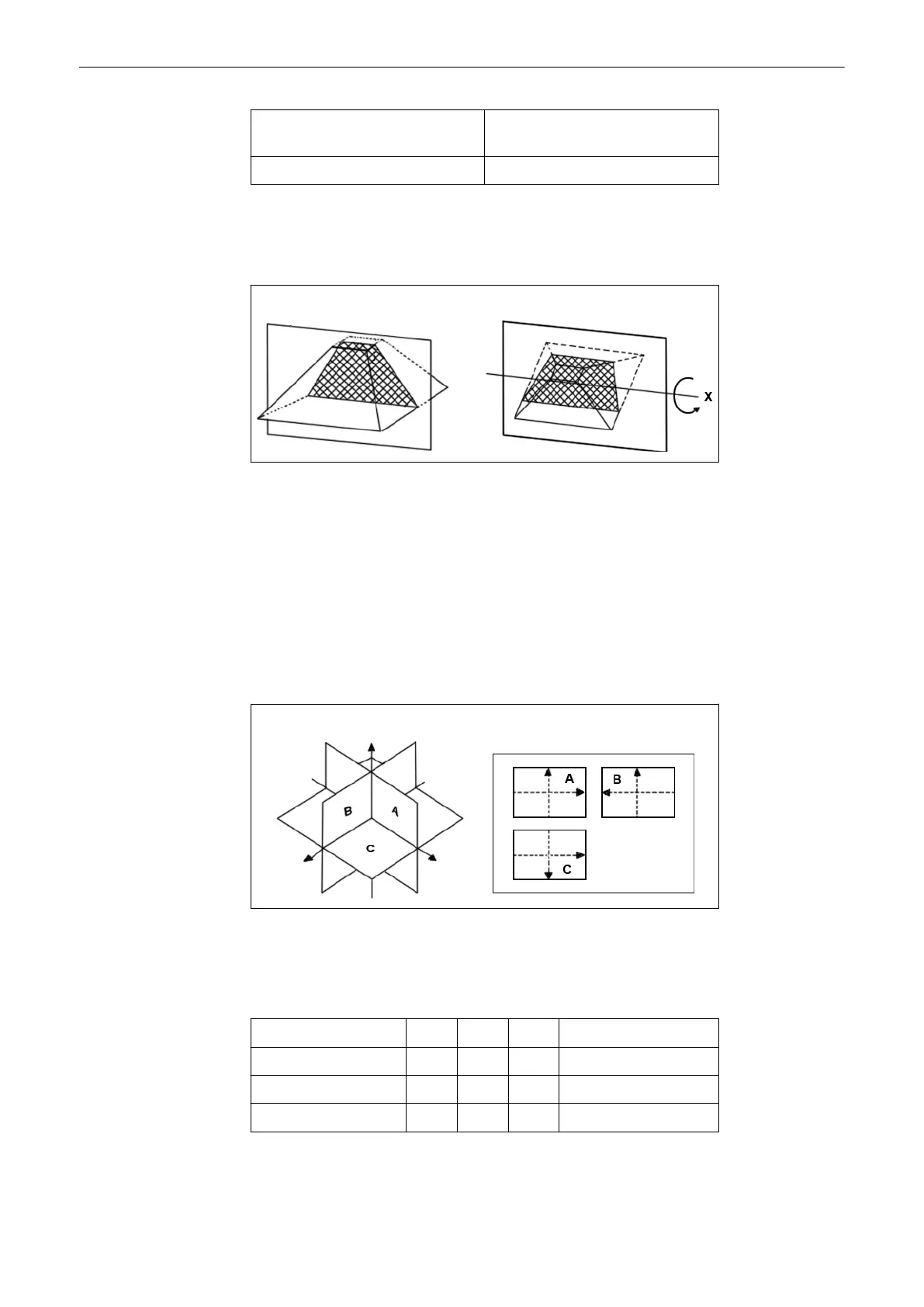
1. Display plane 3. Resultant image of plane within
volume
2. Volume Center plane 4. Displacement
Rotation of the volume body in relation to the display plane:
The rotation can be around the X-axis or the Y-axis of the display plane, or the Z-axis which is
perpendicular to the display plane.
Start situation Rotation (around X-axis)
The position of the volume body in relation to the display plane is determined by a relative
coordinate system. This is made up of three orthogonal axes. The common intersection of
these axes is the central dot. These axes are displayed within the display plane - exactly in the
X-, Y- and Z-directions and colored. Rotation around any of these axes and displacement of
the center of rotation make any imaginable plane within the volume body displayable. The INIT
position of the volume body in relation to the display plane is resettable; it is the start situation
after completion of a volume scan.
The standard representation: 3 sectional planes The 3 orthogonal sectional planes are
simultaneously displayed on the screen. Each quarter of the monitor displays a sectional view
through the volume body as shown below.
Sectional planes A, B, C Display of A, B, C
The intersection lines of the planes are displayed in colors:
AB = blue AC = red BC = yellow
Orientation of intersection lines on the screen:
Section/field A B C
Intersection line AB V V P V = Vertical
Intersection line AC H P H H = Horizontal
Intersection line BC P H V P = Perpendicular
By this definition the relation of the position of the 3 images A, B, C is also indicated (as made
clear by the direction of arrows). The presentation of 3 orthogonal sectional planes may lead to
Volume Mode
Voluson® S6/S8 Basic User Manual
5433669-100 Revision 4 9-25
 Loading...