•
'3D Gray Chroma Map'
on page 9-47
•
'Tint Map'
on page 6-23
•
'Contrast'
on page 9-47
•
'Background'
on page 9-47
•
'Balance'
on page 9-47
•
'Power Threshold'
on page 9-48
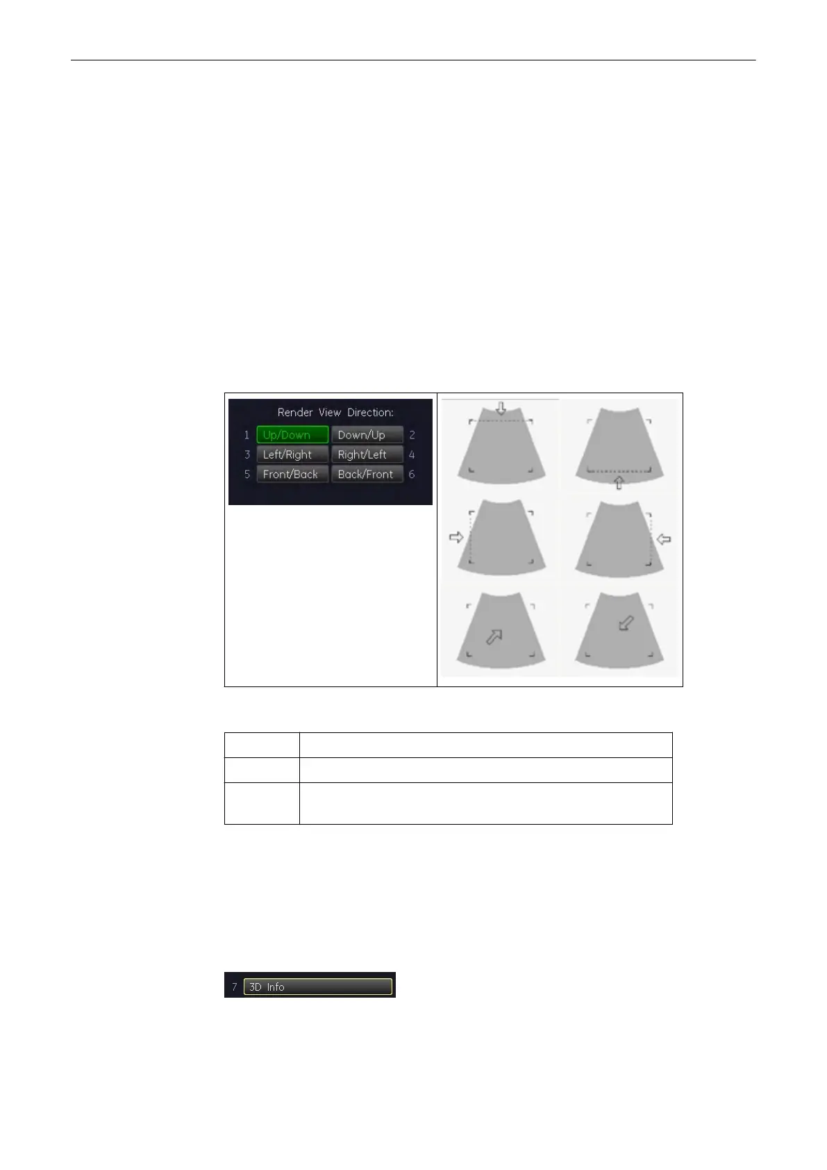
9.3.1 Render View Direction
The 3D render box determines the ROI (region of interest) for the 3D calculation and
determines the direction of view through the volume block. The adjustment of the render box is
done with help of the 3 orthogonal planes A, B and C, each dividing the box in the center.
The direction of the view is adjustable: 'The Render Box'
on page 9-14
Explanation for the Render Box direction Up/Down:
Plane A: The viewing direction is from top to bottom in plane A.
Plane B: The viewing direction is from top to bottom in plane B.
Plane C: The viewing direction is perpendicular on plane C (bird’s eye
view).
The green line of the render box in A- and B-plane symbolizes the direction of view and the
border for starting the analysis.
Note
The Render View Direction keys are not available in Static 3D Sectional Planes mode.
9.3.2 3D/4D Info
On/Off switch to show full or reduced Image Info parameters on screen.
On (full): includes 3D/4D, 2D & CFM Mode Off (reduced): 3D/4D Info only
Volume Mode
Voluson® S6/S8 Basic User Manual
5433669-100 Revision 4 9-45