[Single] screen format key illuminated. The rendered 3D image is magnified and displayed in a
full-size format without the sectional planes A, B, and C.
9.4.1.2 Adjust Position, Size and Curvature of the Render Box
Note
The reference image selector will only be displayed if quad screen display is selected.
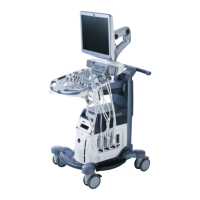
1. Select reference image A, B, C or 3D.
The rotary controls and the trackball are assigned to the reference image for the adjustment of
the render box functions (image position, size of volume box and render start curvature).
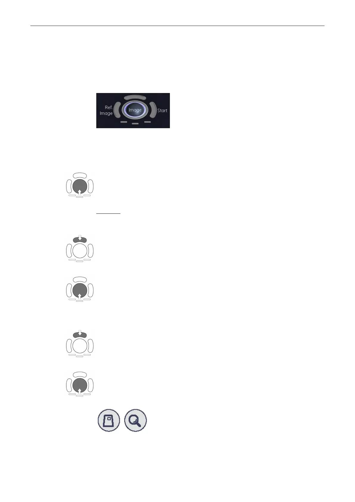
2. By means of the trackball, place the information to be rendered into the box: The selected
image A, B or C is positioned in relation to the render box.
Important:
Structures, which obstruct the free sight to the object, can be positioned out of the box.
3. Press the upper trackball key to change the function from image position to size of the
render box (ROI).
4. Adjust the horizontal and vertical dimension of the render box.
Note
Benefit of a bigger box: higher resolution Benefit of a smaller box: faster calculation time
5. Press the lower left trackball key again to change the function from ROI of the render box
to render start curvature.
6. Move the trackball to adjust the bending (curve) of the “green” render start line.
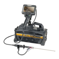
7. The magnifier [Zoom] button varies the size of the contents of the box within image A, B and
C in relation to the render box.
Volume Mode
Voluson® S6/S8 Basic User Manual
5433669-100 Revision 4 9-53