Depending on the “Render Mode” setting, the skin (of the shell contour) or the rendered
volume image within the shell contour is displayed in the lower right quadrant. review: Render
Mode and Display of the Shell Geometry
(chapter
'Render Mode and Display of the Shell
Geometry'
on page 9-129
)
Depending on the “Render Mode” setting, the skin (of the shell contour) or the rendered
volume image within the shell contour is displayed in full size format. review: Render Mode
and Display of the Shell Geometry
(chapter
'Render Mode and Display of the Shell Geometry'
on page 9-129
)
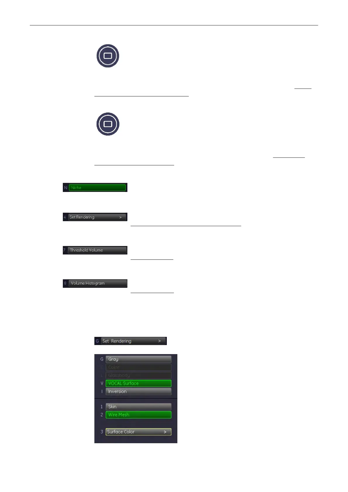
The surface of the (shell) contour is cut up and the slices of the 3D image and
the surface of the (shell) contour is displayed in one image. Select exit the
“VOCAL Niche” menu, select the [Niche] key again.
review:
Render Mode and Display of the Shell Geometr
'Render Mode and Display of the Shell Geometry'
on page 9-129
review:
Threshold Volume
'Threshold Volume'
on page 9-130
review:
Volume Histogram
'Volume Histogram'
on page 9-131
9.12.5.5 Render Mode and Display of the Shell Geometry
1. Select the [Render Mode] key.
Volume Mode
Voluson® S6/S8 Basic User Manual
5433669-100 Revision 4 9-129