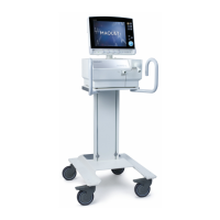
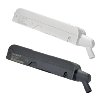
2.4.1 Patient Unit Components
Connections and labels
Refer to the Patient Unit Diagram for the
location of the following numbered
components:
1. Expiratory outlet
2. Gas inlet for air
3. Model number
4. Serial number
5. Manufacturing information
6. UDI label
7. Gas inlet for O
2
8. Cooling fan with filter
9. Label
10. Label
11. Equipotentiality terminal
12. AC power supply connector with fuse
13. User interface connector
14. Fuse for external DC power supply
15. External +12V DC inlet
16. Alarm output connection
17. RS-232 connector
18. Inspiratory outlet
19. Expiratory inlet
SERVO-s VENTILATOR SYSTEM V8.0, User's Manual
29
| System Overview |
2 |
 Loading...