WR1000-UM-251–01–9380 3 – 2
3. DISASSEMBLY AND REASSEMBLY
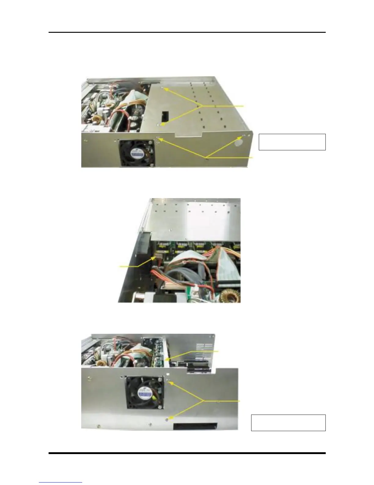
3.2.2 Replacing the Amp DC/DC Board
(1) Remove the control panel unit (see Section 3.3, “Replacing the Control Panel Unit”).
(2) Unfasten the six screws then remove the upper amp chassis.
Fig. 3-2-3
(3) Disconnect the cable from connector P171.
Fig. 3-2-4
(4) Unfasten the four screws, then remove the amp mother assembly by lifting it up and off.
Fig. 3-2-5
P171
M3L4 binding-head
screws
Amp mother assembly
* Also remove the two screws
on the other side
M3L4 binding-head
screws
M3L4 binding-head
screws
* Also remove the two
screws on the other side