WR1000-UM-251–01–9380 5 – 1
5. ADJUSTMENTS
5. ADJUSTMENTS
5.1 Adjusting the V Amp Overshoot
Always perform the overshoot adjustment described below whenever a V amp has been replaced.
Preparations
(1) Have on hand an oscilloscope that can be set to output square waves at a ±2 V output level and a 1-Hz
frequency.
(2) Prior to measurement, mutually connect the GND terminals of the oscillator and the WR1000.
(3) Perform adjustment using a precision screwdriver with a plastic handle. (A precision screwdriver with a
metallic handle cannot be used because it causes noise to mix with the waveforms.)
(4) To perform adjustment, remove the plastic rivet covering the adjustment hole for each trimmer, as shown
in the photograph below.
Fig. 5-1-1
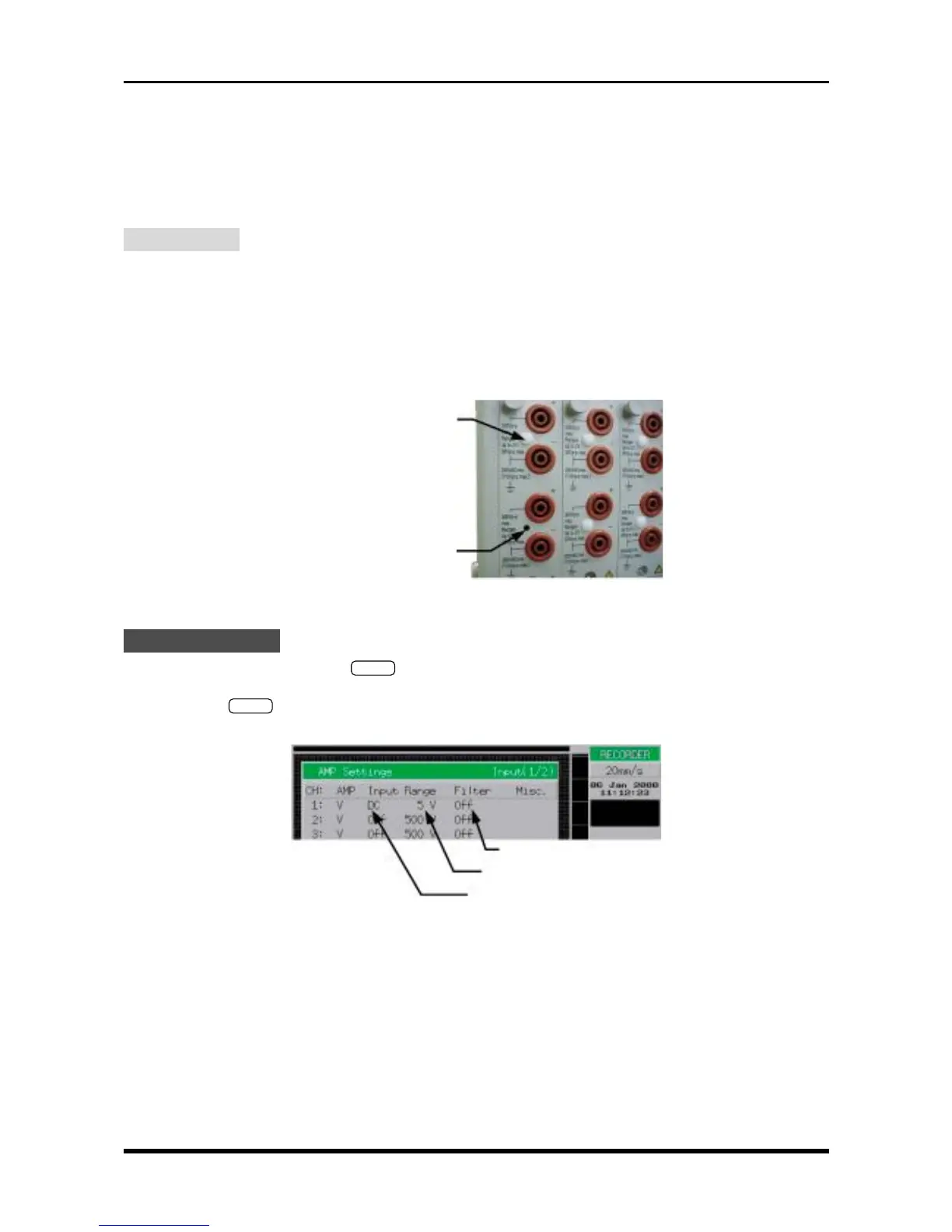
Setting Procedure
(1) Use the main control panel’s
MODE
key to select RECORDER as the measurement mode.
(2) Use the keys at the CHART SPEED section to set the chart speed to 20mm/s.
(3) Press the
INPUT
key on the Conditions panel to open the AMP Settings menu, then change the set-
tings as indicated below.
Fig. 5-1-2
3 × 4.5 ivory plastic rivet
Trimmer adjustment hole
Filter: Off
Range: 5V
Input: DC for the channel to be adjusted;
set all other channels to Off