WR1000-UM-251–01–9380 3 – 36
3. DISASSEMBLY AND REASSEMBLY
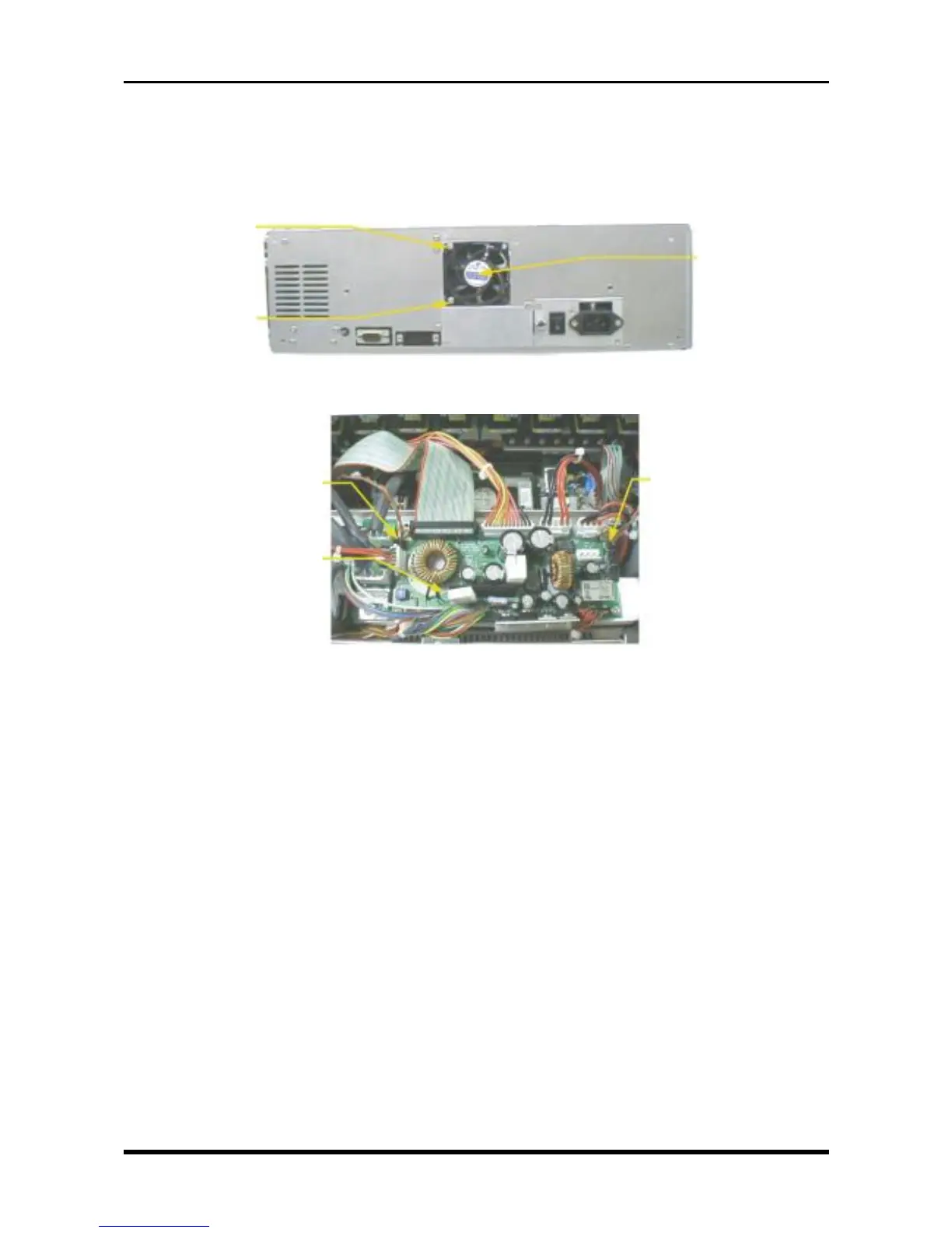
3.8 Replacing the Fans
(1) Remove the control panel unit (see Section 3.3, “Replacing the Control Panel Unit”).
(2) Unfasten the two screws, disconnect the cables from the two connectors on the system power board,
then replace each fan.
Fig. 3-8-1
Fig. 3-8-2
M3L20 binding-
head screw
M3L20 binding-
head screw
Fan assembly
P414
(the fan near the Power switch)
System power board
P413 (the fan near the front)