WR1000-UM-251–01–9380 3 – 43
3. DISASSEMBLY AND REASSEMBLY
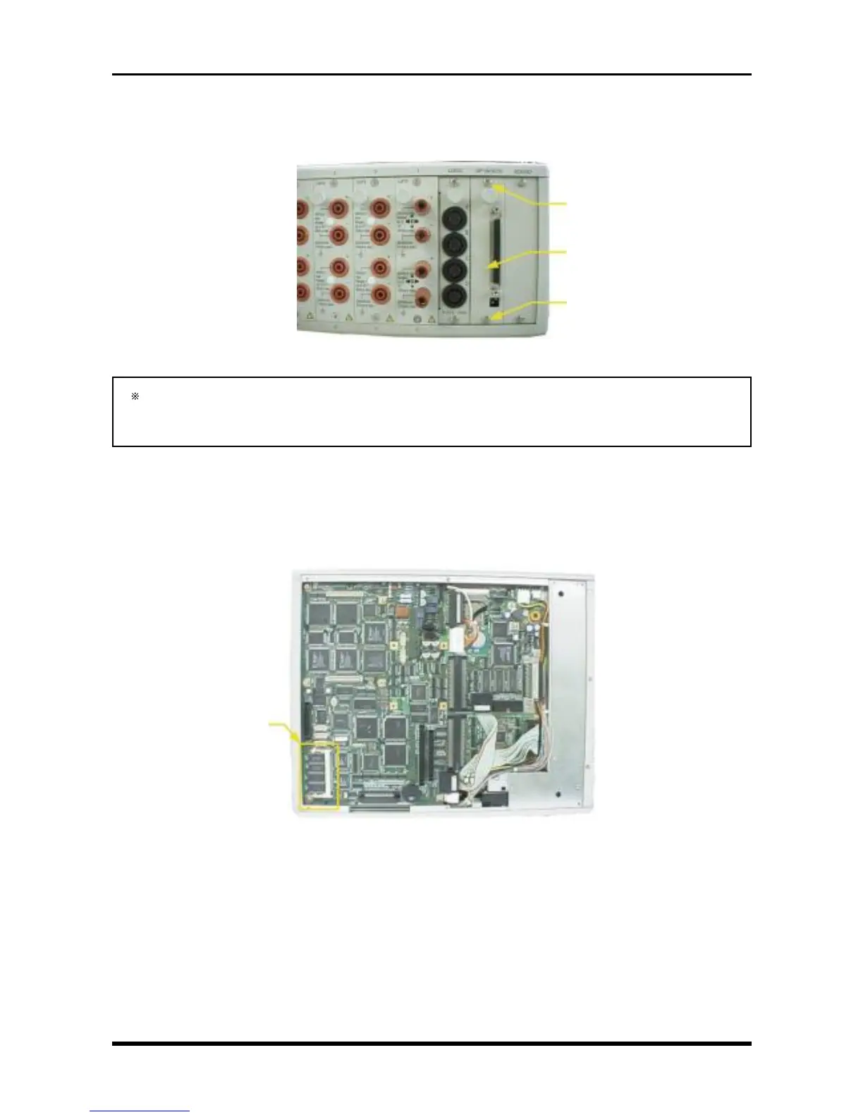
3.10 Replacing the Interface Board
Unfasten the two screws, then replace the interface board.
Fig. 3-9-11
After replacing the SCSI interface, be sure to set the Terminator setting’s switches to the same setting
as before replacement. If an external device is not connected to the SCSI interface when checking
the SCSI interface’s operation, however, temporarily set both switches to the ON position.
3.11 Replacing the Memory Expansion Board
(1) Remove the bottom plate (see Subsection 3.6.1, “Replacing the 16-CH Control Board”).
(2) Replace the memory expansion board.
Fig. 3-9-12
M3L4 binding-head screw
SCSI interface
M3L4 binding-head screw
Memory expansion unit