WR1000-UM-251–01–9380 6 – 3
6. INSPECTION AND CHECK PROCEDURES
6.2 Inspection and Check Methods
6.2.1 Insulation Resistance
Use a megaohm meter (an insulation resistance gauge) to check that the insulation resistance between the
following terminals are equal to or higher than the rated values.
(1) Between the AC input and GND terminals:
Using a megaohm meterr with an output capacity of 1000 VDC, check that the measured insulation
resistance is 100 MΩ or more.
(2) Between the signal input and GND terminals:
Using a megaohm meter with an output capacity of 500 VDC, check that the measured insulation resis-
tance is 100 MΩ or more.
6.2.2 Dielectric Strength
Using a dielectric strength tester to apply an experimental voltage between the following terminals, check that
the current equals or is lower than the rated value within the stipulated time.
(1) Between the AC input and GND terminals:
After applying an experimental voltage of 2.3 kVAC rms for no more than two seconds, check that the
value of the current sustained for two seconds is:
• 15 mA or less for an eight-channel model; or
• 20 mA or less for a 16-channel model.
(2) Between the signal input and GND terminals:
After applying an experimental voltage of 2.3 kVAC rms for no more than two seconds, check that the
value of the current sustained for two seconds is 2 mA or less.
6.2.3 Voltage Precision
Supply the reference voltage determined for each measurement range to each installed amp, then check the
voltage precision.
Preparation
• Use a voltage generator that can output up to 500 VDC (using four-digit settings).
• Mutually connect the ground terminals of the voltage generator and WR1000 prior to initiating measurement.
Setting Procedure
(1) Press the main control panel’s
MODE
key to select LOGGING as the measurement mode.
(2) Press the
RECORD
key on the Conditions panel to respectively display the Record Settings and Format
Settings windows. To enter the following settings at each window, use the arrow keys to move the cursor
to the desired parameter, then use the
ENTER
key and arrow keys to enter the desired settings.
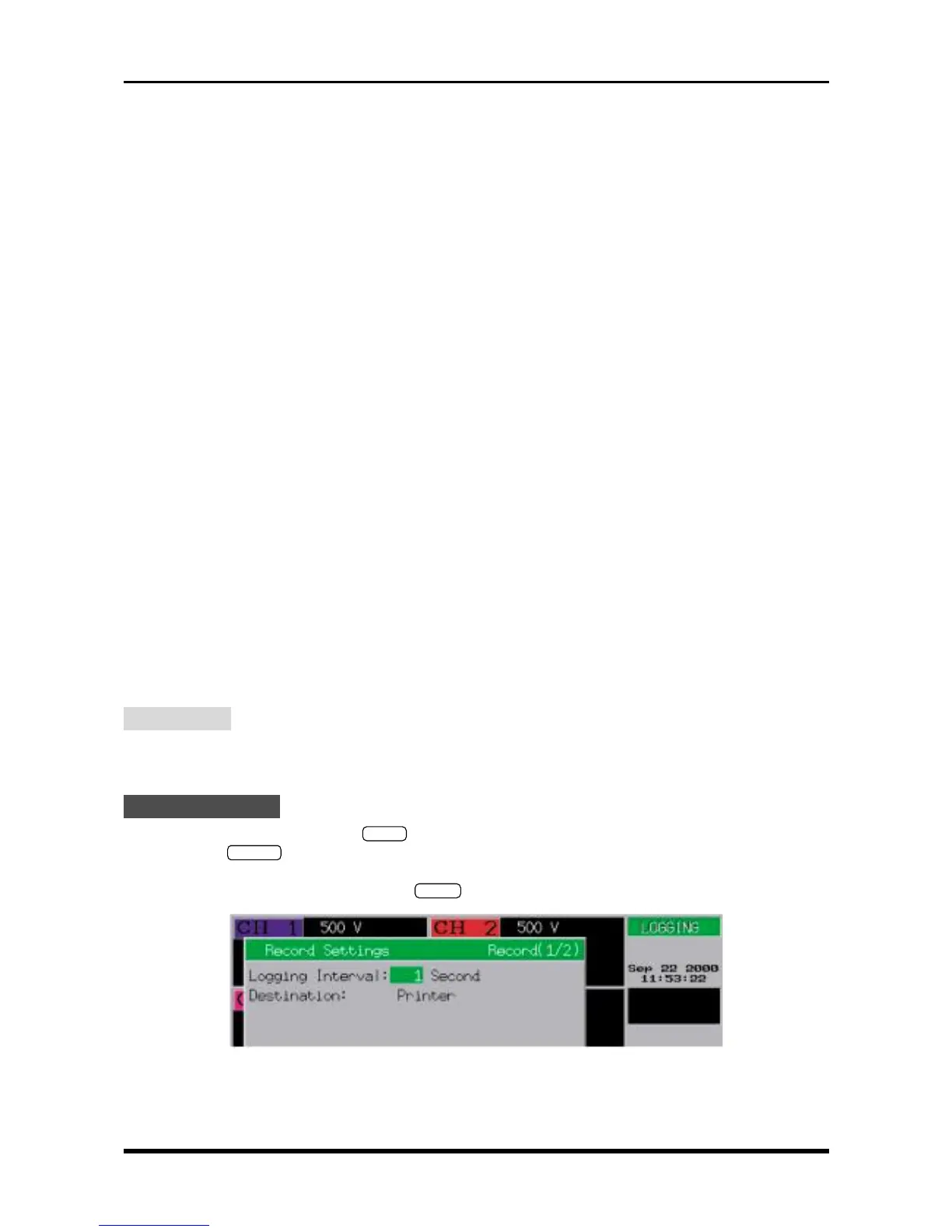
Fig. 6-2-1. Record Settings window
Logging Interval : 1 Second
Destination : Printer