WR1000-UM-251–01–9380 3 – 19
3. DISASSEMBLY AND REASSEMBLY
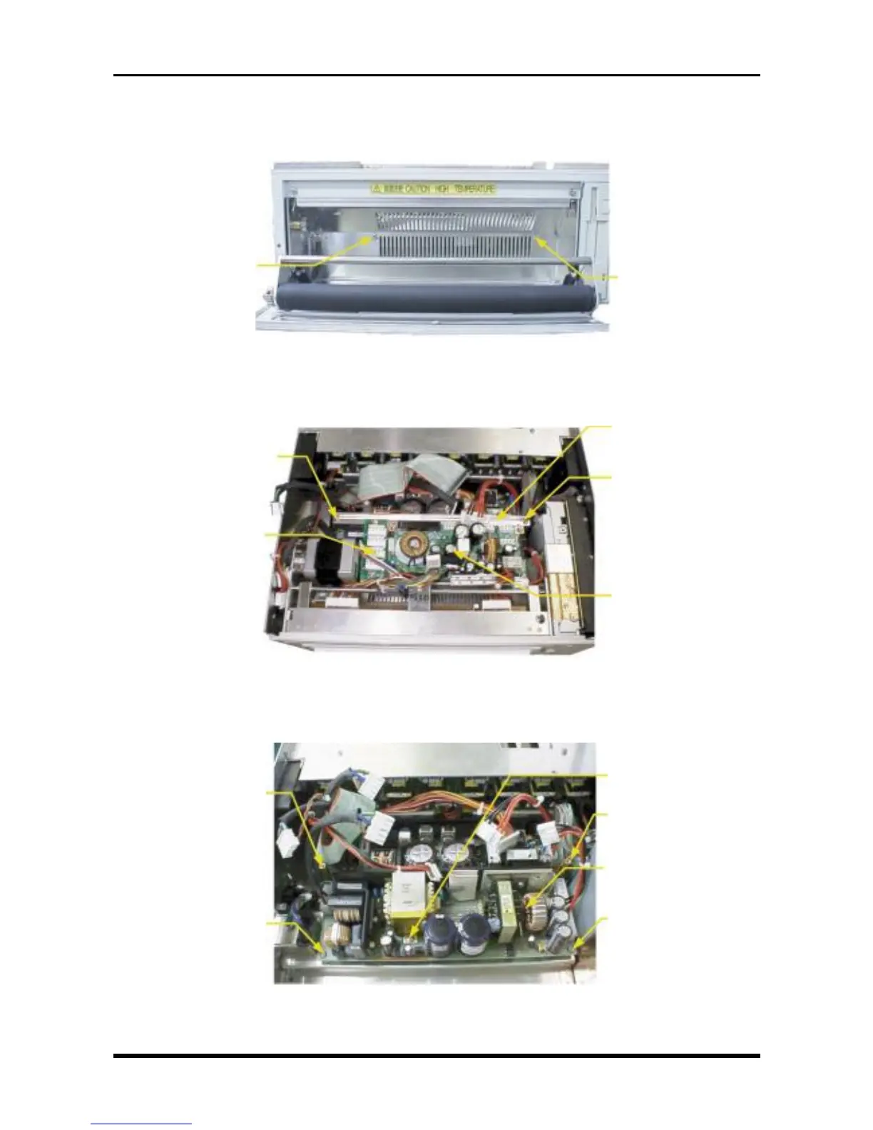
3.4.2 Replacing the Power Unit for Channels 1 to 8
(1) Open the printer cover, then unfasten the two screws.
Fig. 3-4-2
(2) Disconnect the cables from all connectors on the system power board and AC relay board, unfasten the
two screws, then remove the power chassis.
Fig. 3-4-3
(3) Unfasten the three screws, remove the two supports, then replace the power unit for channels 1 to 8.
Fig. 3-4-4
M3L4 binding-head
screw
M3L4 binding-head
screw
M3L4 binding-head screw
AC relay board
Power chassis
M3L4 binding-head screw
System power board
M3L4 binding-head
screw
Power support
Power unit for channels
1-8 (ZWS150PF-24)
M3L4 binding-head
screw
M3L4 binding-head
screw
Power support