WR1000-UM-251–01–9380 3 – 21
3. DISASSEMBLY AND REASSEMBLY
3.5 Replacing the Printer Unit
3.5.1 Replacing the Thermal Print Head
Always conduct the Setup operation for specifying the resistance of the thermal printhead whenever the ther-
mal printhead has been replaced.
(1) Remove the control panel cover (see Section 3.3, “Replacing the Control Panel Unit”).
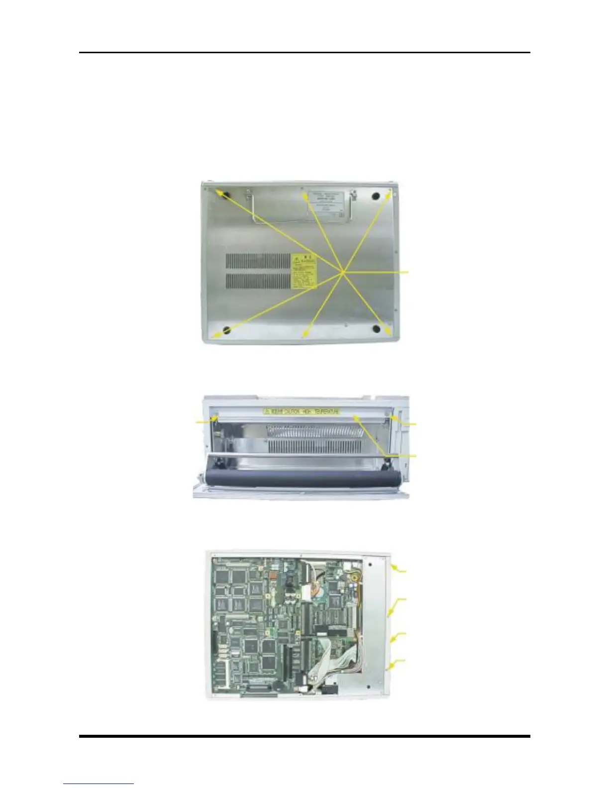
(2) Unfasten the six screws then remove the bottom plate.
Fig. 3-5-1
(3) Open the printer cover, then unfasten the two screws.
Fig. 3-5-2
(4) Unfasten the three screws on the bottom panel, then remove the printer unit mold.
Fig. 3-5-3
M3L5 countersunk-head
screws
M3L5 countersunk-head
screw
M3L5 countersunk-head
screw
Printer unit mold
M3L5 countersunk-head
screw
M3L4 binding-head
screw
Printer unit mold
M3L4 binding-head
screw