WR1000-UM-251–01–9380 3 – 22
3. DISASSEMBLY AND REASSEMBLY
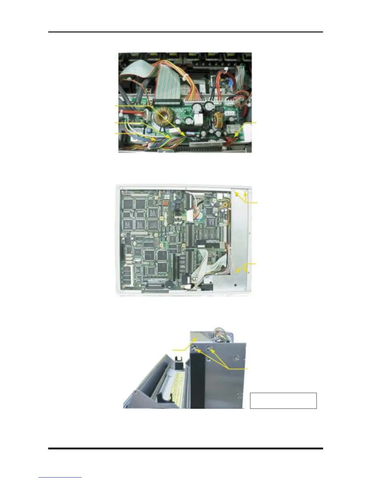
(5) Disconnect the cables from the four connectors on the system power board.
Fig. 3-5-4
(6) Unfasten the four screws, then remove the printer unit.
Fig. 3-5-5
(7) Unfasten the two screws each on the right and left sides, then remove the head pressure support.
Fig. 3-5-6
M3L6 countersunk-
head screws
M3L6 countersunk-
head screws
Head pressure support
M3L6 countersunk-
head screws
* Also unfasten the two
screws on the other side.
P405
P409
P410
P407