WR1000-UM-251–01–9380 6 – 6
6. INSPECTION AND CHECK PROCEDURES
6.2.4 Temperature Precision (M Type Amps Only)
This inspection is only performed for M type amps.
Preparation
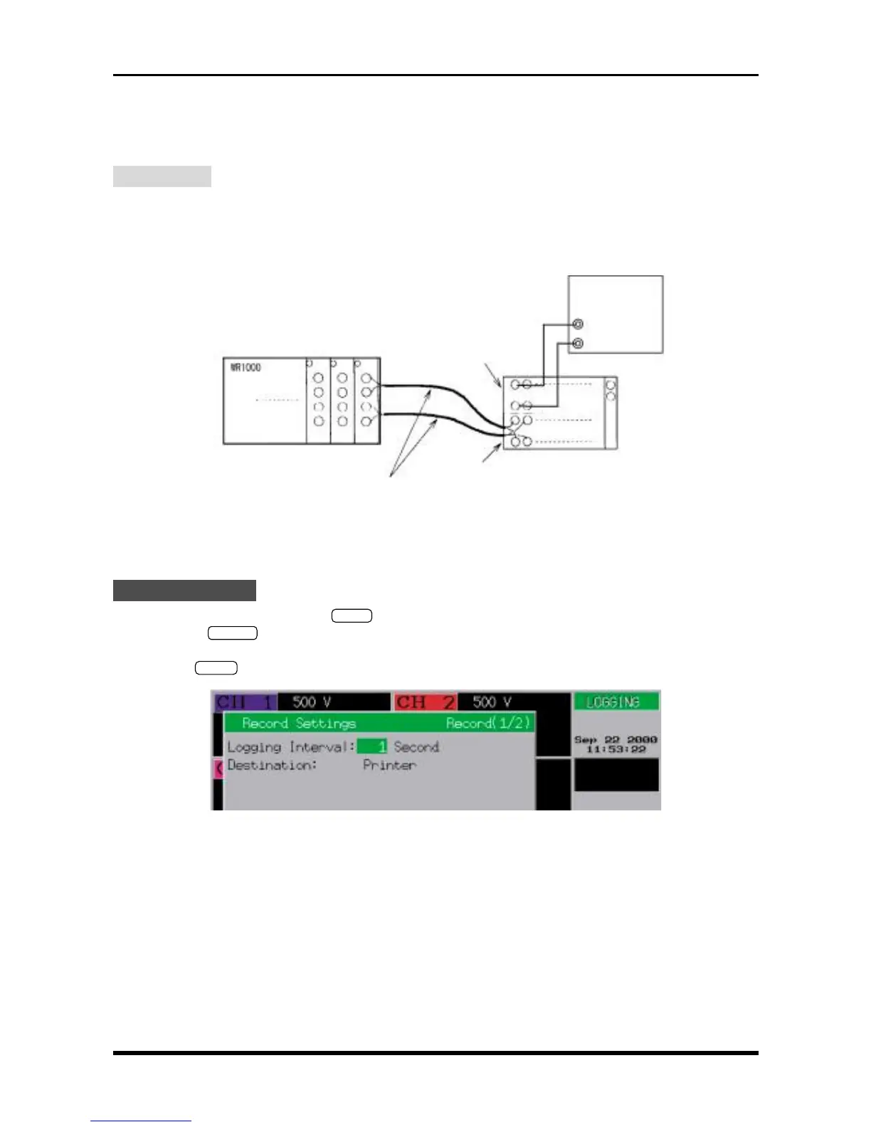
• Use (T) temperature compensation leads to connect the target amp and a 0°C reference temperature
device (zero control) as shown below.
• As shown below, use copper leads to connect the 0°C reference temperature device (zero control) to a
voltage generator that can specified for output up to 1 µV.
NOTE : Use one compensating copper lead to connect each terminal as shown
in the above figure. (Parallel wiring is not permitted.)
Fig. 6-2-4
Setting Procedure
(1) Press the main control panel’s
MODE
key to select LOGGING as the measurement mode.
(2) Press the
RECORD
key on the Conditions panel to respectively display the Record Settings and Format
Settings windows. At each window, use the arrow keys to move the cursor to the desired parameter, then
use the
ENTER
key and arrow keys to enter the following settings.
Fig. 6-2-5. Record Settings window
Logging Interval : 1 Second
Destination : Printer
Voltage generator
(T) output side
(T) input side
(T) compensating copper leads
0°C reference
temperature device
(zero control)
+
-
+
-
+
-