WR1000-UM-251–01–9380 5 – 2
5. ADJUSTMENTS
Adjustment Procedure
(1) Using the oscillator, output signals consisting of square waves ( ) at a ±2 V output level and a 1-Hz
frequency for input to the WR1000.
(2) Press the main control panel’s
START
key to start measurement. Adjust the trimmer until overshoot is
eliminated.
Before adjustment
Fig. 5-1-3
After adjustment
Fig. 5-1-4
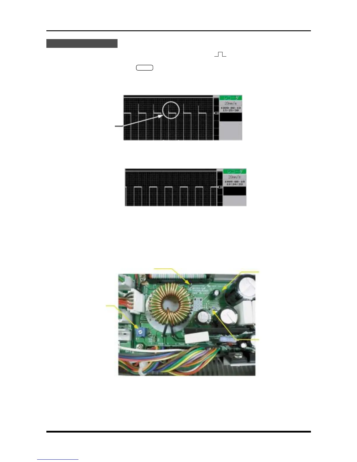
5.2 Adjusting the Overcurrent Monitoring Operation
Whenever the system power board has been replaced, adjust the VR1 trimmer so that TP5 becomes 1 V
under zero load (0 V).
Fig. 5-2-1
Overshoot
System power board
TP2 (GND)
VR1
TP5