WR1000-UM-251–01–9380 6 – 14
6. INSPECTION AND CHECK PROCEDURES
6.2.7 Memory Trigger Operation
Preparation
• Have on hand an oscillator capable of the types of output described below.
Output waveforms : sine waves, triangular waves
Frequency : 5 Hz and 2 Hz
• Mutually connect the GND terminals of the oscillator and the WR1000 before measurement.
Setting Procedure
(1) Press the main control panel’s
MODE
key to select RECORDER as the measurement mode.
(2) Press the
MEMORY
key on the Conditions panel to respectively display the Memory Settings and Data
Replay Settings windows. At each window, use the arrow keys to move the cursor to the desired param-
eter, then use the
ENTER
key and arrow keys to enter the following settings.
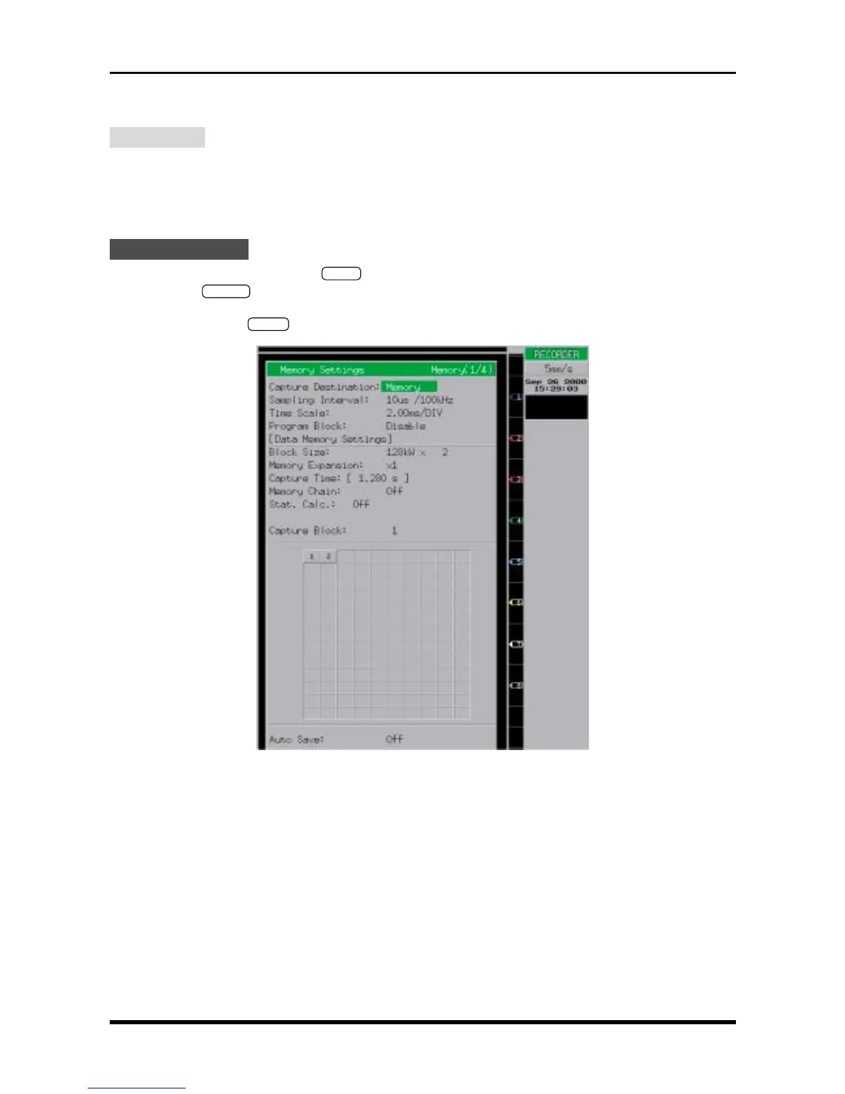
Fig. 6-2-17. Memory Settings window
Capture Destination Memory
Sampling Interval 10µs/100kHz
Block Size 128kW × 2 (or 256kW × 2 if the memory option is installed)
Memory Expansion ×1
Memory Chain Off
Stat. Calc. Off
Capture Block 1 or 2 (see Steps (1) and (6) under “Measurement”)
Auto Save Off