WR1000-UM-251–01–9380 6 – 13
6. INSPECTION AND CHECK PROCEDURES
Measurement
(1) Set the Filter parameter to Off, then adjust the oscillator’s output level to achieve an appropriate ampli-
tude when the oscillator is inputting a 1-Hz frequency (the reference signal input).
(2) In the above status, turn on the printer and then record (print) the amplitude of the reference signal input.
(3) Specify the Filter setting and the input signal frequency from the oscillator according to Table 6-2-5. (Set
the output level to match that of the reference signal input.)
(4) Check that the measured amplitude is within the standard when compared with the amplitude during
reference signal input.
Table 6-2-5
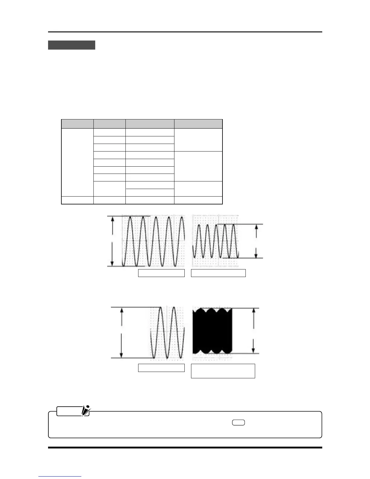
Reference signals Signals after filtering
B
Measured result = — × 100 [%]
A
Fig. 6-2-15
Reference signals Signals at 50kHz (V amp)
or 20kHz (M amp)
B
Measured result = — × 100 [%]
A
Fig. 6-2-16
NOTE
To measure Channels 9 through 16, press the amp control panel’s
SEL
key to switch the channel
group displayed, then resume measurement.
A
B
Input Filter Input frequency Standard
Line 1.5 Hz
5 Hz 5 Hz 55 to 85%
10 Hz 10 Hz
30 Hz 30 Hz
DC 50 Hz 50 Hz
60 to 80%
500 Hz 500 Hz
5 kHz 5 kHz
Off
V: 50 kHz
70 to 112%
M: 20 kHz
AC Off 10 Hz 60 to 80%
B
A