WR1000-UM-251–01–9380 6 – 12
6. INSPECTION AND CHECK PROCEDURES
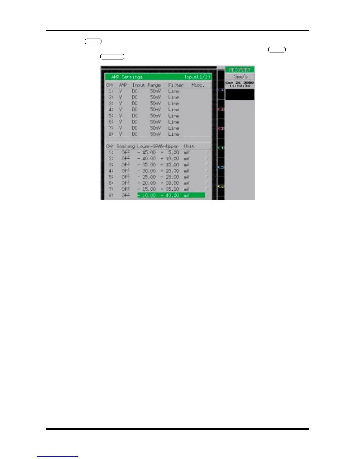
(3) Press the
INPUT
key on the Conditions panel to display the AMP Settings window shown below. Use
the arrow keys to move the cursor to the desired parameter, then use the arrow keys,
ENTER
key, jog/
shuttle dial, and
EXECUTE
key to enter the following settings.
Fig. 6-2-14. AMP Settings window
AMP V or M
Input DC
Range 5V
Filter The same Filter setting as the object of measurement
Scaling Off
Lower-SPAN-Upper Specify an appropriate pitch that will enable simultaneous viewing of eight lines