WR1000-UM-251–01–9380 3 – 8
3. DISASSEMBLY AND REASSEMBLY
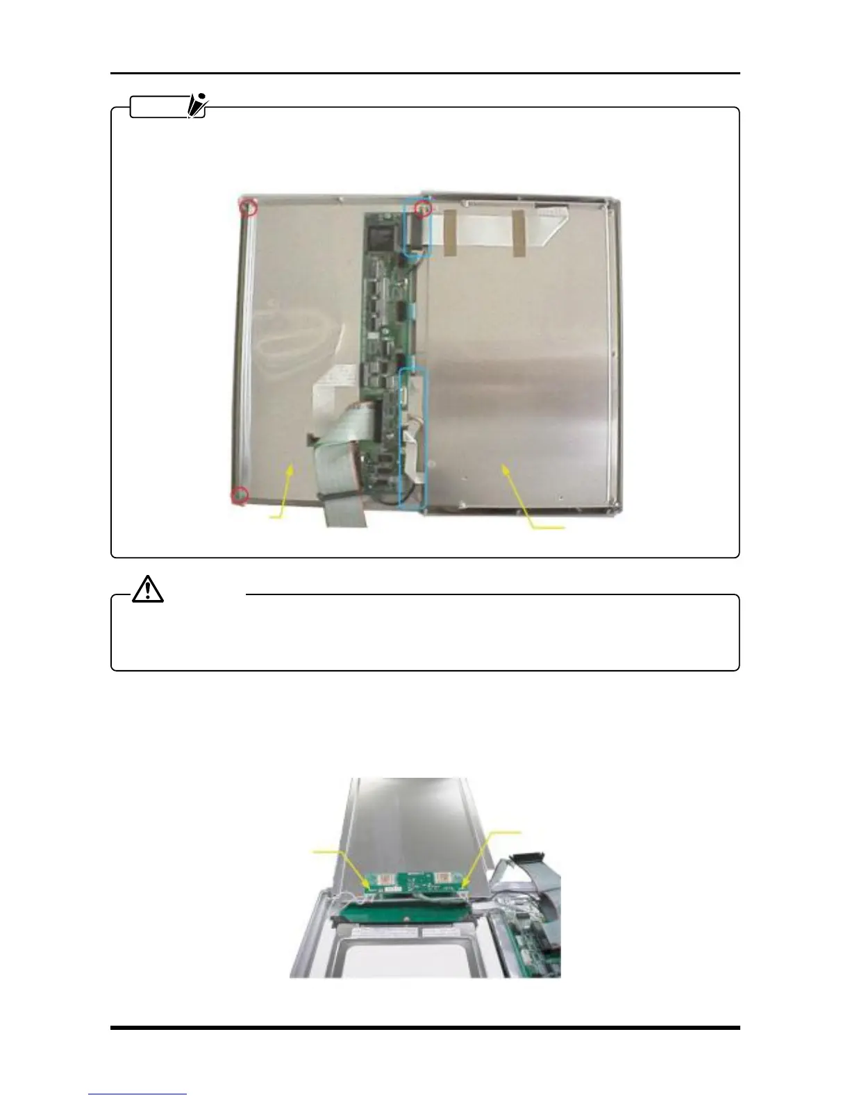
NOTE
When remounting the LCD shield plate, ensure that the circled areas in the photograph below are cov-
ered by the control panel shield and fasten both screws at the same time. (Also tighten the ground lead
at the same time.)
Fig. 3-3-7
CAUTION
When removing or mounting the control panel shield either while replacing the inverter board or while
cleaning or replacing the main control panel’s keys, because the red circled areas are not present on the
protective sheet applied to the control panel shield, be careful not to cut your fingers on the corners.
3.3.2 Replacing the LCD Panel
(1) Remove the LCD shield plate (see Subsection 3.3.1, “Replacing the Inverter Board”).
(2) Disconnect the two cables from connectors CN2 and CN3 on the inverter board.
Fig. 3-3-8
LCD shield plate
Control panel shield
CN2
CN3