WR1000-UM-251–01–9380 3 – 7
3. DISASSEMBLY AND REASSEMBLY
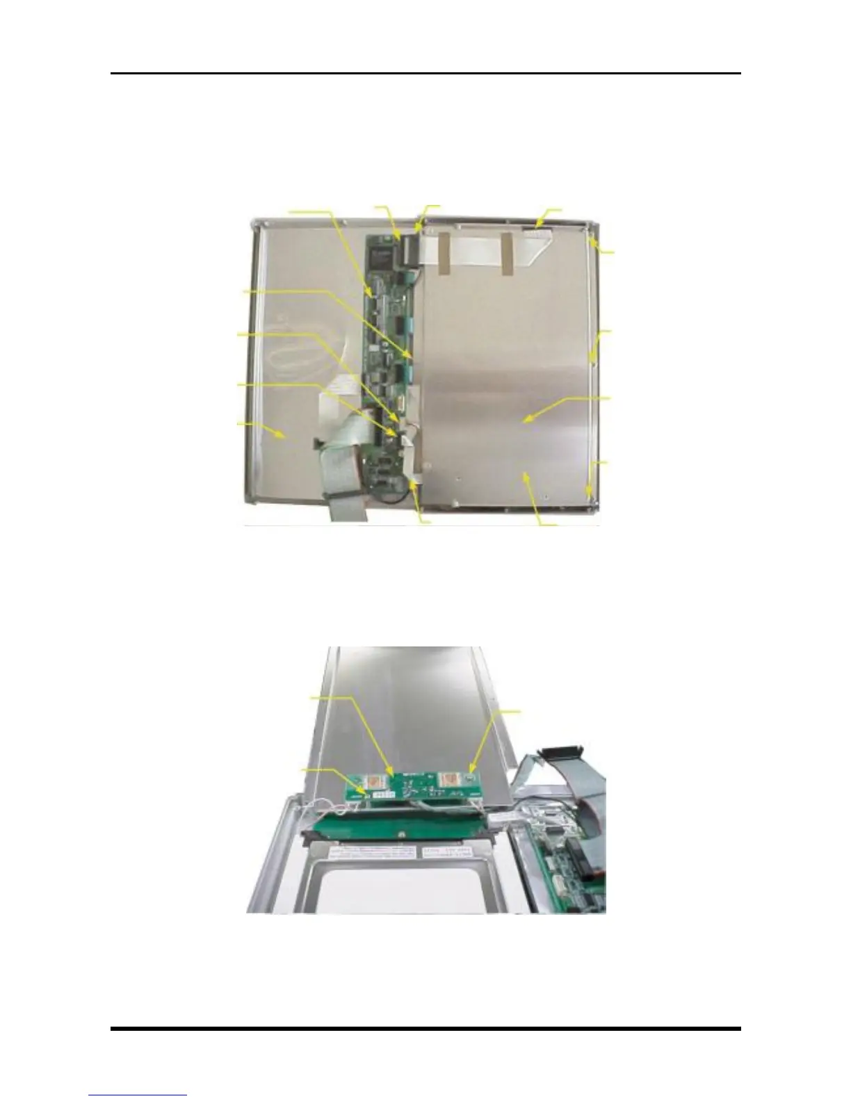
3.3.1 Replacing the Inverter Board
(1) Disconnect the flexible printed circuit cable (FC, WR1000-05) at both ends (from connector P66 on the
key control board and from the LCD relay board).
(2) Disconnect the cables from connectors P61 and P64.
Fig. 3-3-5
(3) Unfasten the six screws, then remove the LCD shield plate.
(4) Remove the two screws and disconnect the cables from connectors CN1, CN2, and CN3, and then
replace the inverter board.
Fig. 3-3-6
M2.6L4 binding-head screw
Inverter board
M2.6L4 binding-head screw
M3L4 binding-head
screw
Key control board
M3L4 binding-head
screw
P61
P64
Control panel shield
M3L6 binding-
head screwP66
LCD relay board
LCD shield plate
LCD sheild plate
M3L4 shield-head
screw
M3L6 binding-
head screw
M3L4 binding-head
screw