WR1000-UM-251–01–9380 3 – 17
3. DISASSEMBLY AND REASSEMBLY
3.4 Replacing the Power Unit
Before replacing any of the boards in the power unit, first remove the control panel unit (see Section 3.3,
“Replacing the Control Panel Unit”).
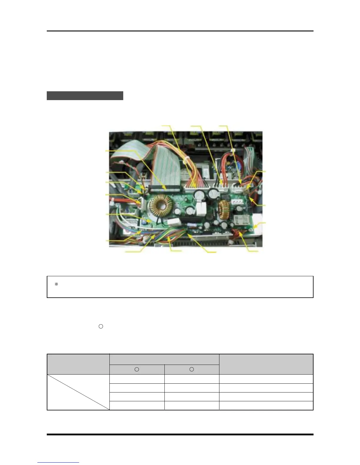
3.4.1 Replacing the System Power Board
Replacement Procedure
Disconnect the cables from 11 connectors and unfasten the four screws, then replace the system power
board.
Fig. 3-4-1
After replacing the system power board, be sure to perform the adjustment described in Section 5.2,
“Adjusting the Overcurrent Monitoring Operation.”
Check Procedures
(1) Short check
Regarding the “
-
” mark as the minus side of the multimeter, use the multimeter to check the voltage
between the connector pins specified in the following table.
Table 3-4-1. Short check
Connector pin no.
Checkpoint
Remarks
+
-
TP1 TP2 +24 V
TP3 TP2 +12 V
TP4 TP2 +5 V
TP6 TP2 +3.3 V
M3L4 binding-head screw
System power board
M3L4 binding-head
screw
M3L4 binding-head screw
P403
P414
P401
P410
P408
P409
P402 P412
P405 P407
P413
M3L4 binding-head
screw