WR1000-UM-251–01–9380 3 – 16
3. DISASSEMBLY AND REASSEMBLY
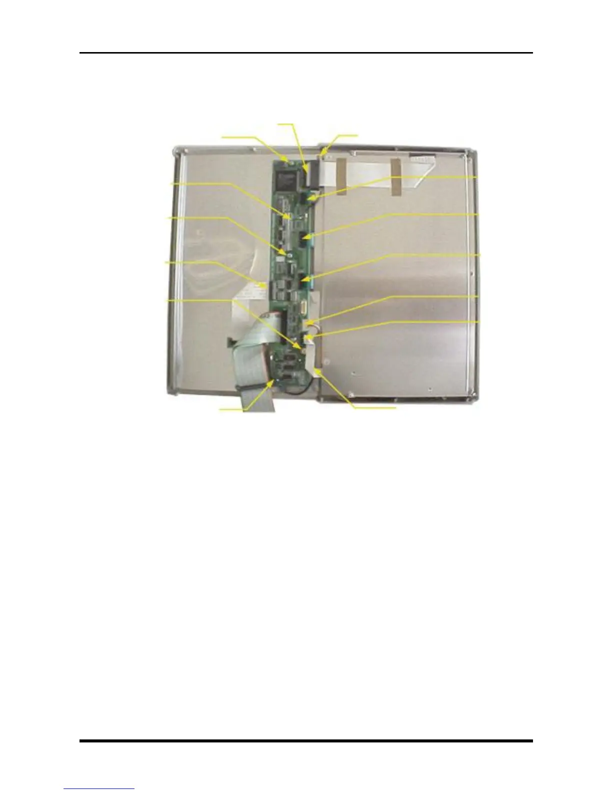
(2) Disconnect the FPC (Flexible Printed Circuit) cables from seven connectors.
(3) Unfasten the two screws at the positions indicated by the * (asterisk) symbol.
(4) Unfasten the four screws, then replace the key control board.
Fig. 3-3-22
M3L4 tapping screw
P66
P69
P68
P65
P62
P61
P64
*M3L6 binding-head screwM3L4 tapping screw
Key control board
M3L4 tapping screw
M3L4 tapping screw
*M3L6 binding-head screw