WR1000-UM-251–01–9380 6 – 18
6. INSPECTION AND CHECK PROCEDURES
6.2.8 REMOTE Interface Operation
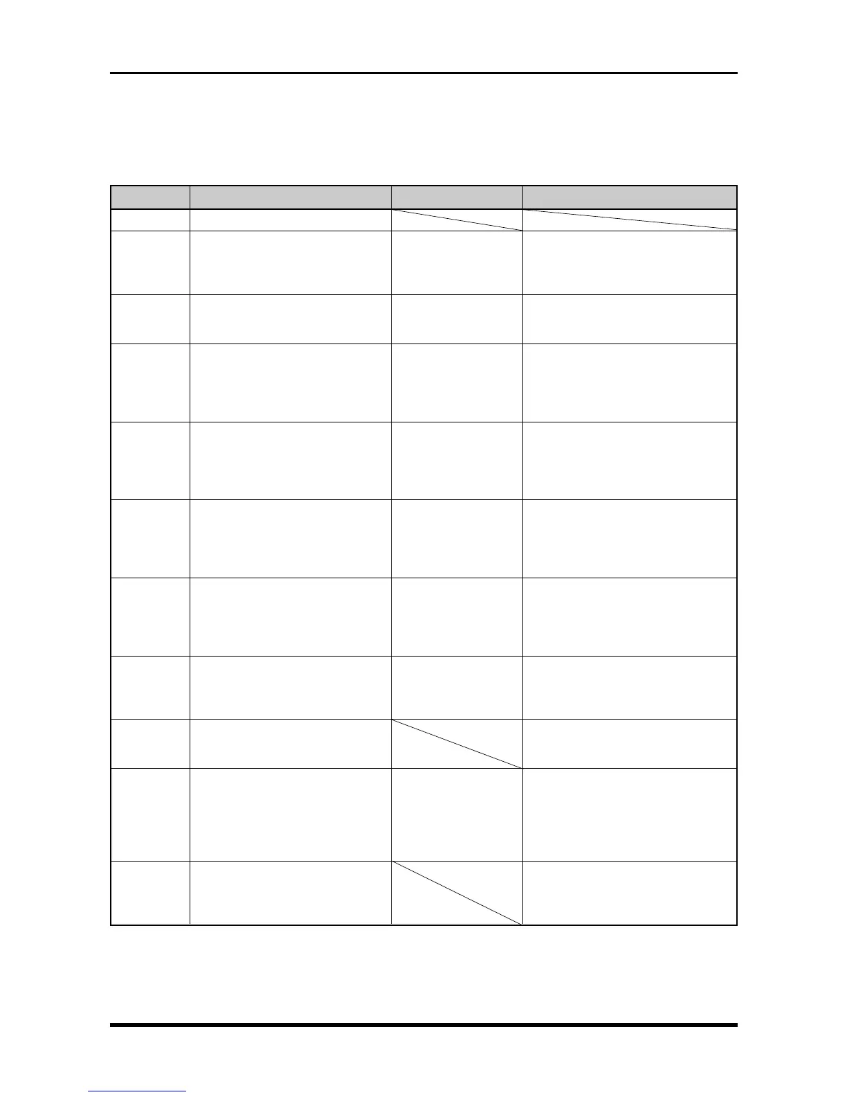
Check that the REMOTE functions operate properly as described in the table below.
Table 6-2-7. Checkpoints of REMOTE interface operation
Pin No.
9~12, 15, 16
1
2
3
4
5
13
6
7
8
16
Function
GND
START/STOP (Level operation)
Measurement starts when a low
signal is input, and stops when a
high signal is input.
START/STOP (Edge operation)
Measurement alternately starts or
stops when a low signal is input.
FEED CLOCK
Inputs chart feed clock pulses
• Feed distance: 0.03125 mm/pulse
• Frequency: 640 pps maximum
• Maximum speed: 20 mm/s
TRIGGER INPUT
Inputs externally-supplied trigger
signals
The trigger is activated when the
signal goes low
SAMPLE CLOCK
Inputs externally-supplied sample
clock pulses
• Pulse width: 500 ns or more
• Cycle : 10 µs or more
EVENT INPUT
Inputs externally-supplied Event
signals
• Pulse width: the recording cycle
or higher
TRIGGER OUTPUT
Outputs Trigger signals
A low pulse is output whenever the
trigger is activated
M/C ALARM
Outputs a low signal whenever an
error occurs.
GO/NOGO OUTPUT
Outputs waveform judgement
signals
• Outputs a low pulse when a
judgement is reached
• Pulse width: 100 ms minimum
AC LINE FAIL OUTPUT
Outputs a high signal during AC
operation, or a low signal during
DC operation.
Settings
Measurement mode:
RECORDER
Measurement mode:
RECORDER
Measurement mode:
RECORDER
Chart Speed: External
(Record Settings
window)
Measurement mode:
RECORDER
Source: External
(Trigger Settings
window)
Measurement mode:
RECORDER
Sampling Interval:
External (Memory
Settings window)
Measurement mode:
RECORDER
Marker: Event (Record
Settings window)
Measurement mode:
RECORDER
Refer to the separate
”Checking the Judge-
ment Output”
Check method
Check that measurement properly
starts and stops
Check that measurement properly
starts and stops
Input 640-Hz pulses and check that
the actual chart speed is 20 mm/s
Check that the trigger is activated
Input clock pulses of 0 to 5 V at a
100-kHz frequency and check that
they are properly captured in memory
Input clock pulses of 0 to 5 V at a 1-
Hz frequency and check that they are
properly printed on chart paper
Check that the pulse is output for at
least 10 ms
Check that a low signal is output when
the printer unit runs out of paper
Same as the left
(for firmware version no. 1.10 and
higher)
* Only applies when the DC adapter
option is installed
Check that the signal output conforms
to the specifications on the left