WR1000-UM-251–01–9380 3 – 34
3. DISASSEMBLY AND REASSEMBLY
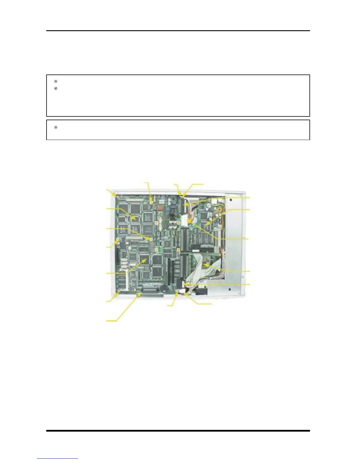
3.6.2 Replacing the Main Control Board
(1) Remove the bottom plate (see Subsection 3.6.1, “Replacing the 16-CH Control Board”).
(2) Remove the front cover (see Section 3.3, “Replacing the Control Panel Unit”).
If the FDD (Floppy Disk Drive) is installed, remove the FDD control board.
If the SCSI interface and either the MODD (Magneto-Optic Disk Drive) or HDD (Hard Disk Drive) is
installed, remove the SCSI control board.
For instructions on removing the above-mentioned memory devices, see Section 3.9, “Replacing the
Internal and External Memory Devices.”
If you have a 16-channel model, remove the 16-CH control board (see Subsection 3.6.1, “Replacing
the 16-CH Control Board”).
(3) Unfasten the seven screws (or, with a 16-channel model, the three screws and four spacers), disconnect
the cables from the four connectors (also disconnect the cable from P1019 if the FDD control board is
mounted and from P1026 if the SCSI control board is mounted), then replace the main control board.
Fig. 3-6-3. For the 16-channel model with FDD and HDD
P1021
SCSI control board
P1022
FDD control board
P1026 (only if the SCSI
control board is mounted)
M3L4 binding-head screw
SQ-6 spacer
16-CH control board
M3L4 binding-head screw
SQ-6 spacer
M3L4 binding-head screw
SQ-6 spacer
Main control board
M3L4 binding-head screw
P1007
M3L4 binding-
head screw
P1019 (only if the FDD control
board is mounted)
M3L4 binding-head screw
P1023
M3L4 binding-head screw
SQ-6 spacer