WR1000-UM-251–01–9380 6 – 8
6. INSPECTION AND CHECK PROCEDURES
Measurement
(1) Turn on the printer.
(2) Use the voltage generator to successively input the reference voltage signals for each range to the 0°C
reference temperature device (zero control) according to the table below, then check that the printed
level of measurement is within the rating.
Temperature ranges:
Standard 1 : When measurement is continued right after setup
-
200°C to 0°C: ± (0.5% of rdg + 1.5°C)
0°C to 400°C: ± (0.2% of rdg + 1.5°C)
Standard 2 : When measurement is continued under different conditions than setup (main unit, mea-
surement site, insertion slot)
-
200°C to 0°C: ± (0.5% of rdg + 2.0°C)
0°C to 400°C: ± (0.2% of rdg + 2.0°C)
Table 6-2-3. M amp: temperature precision ratings
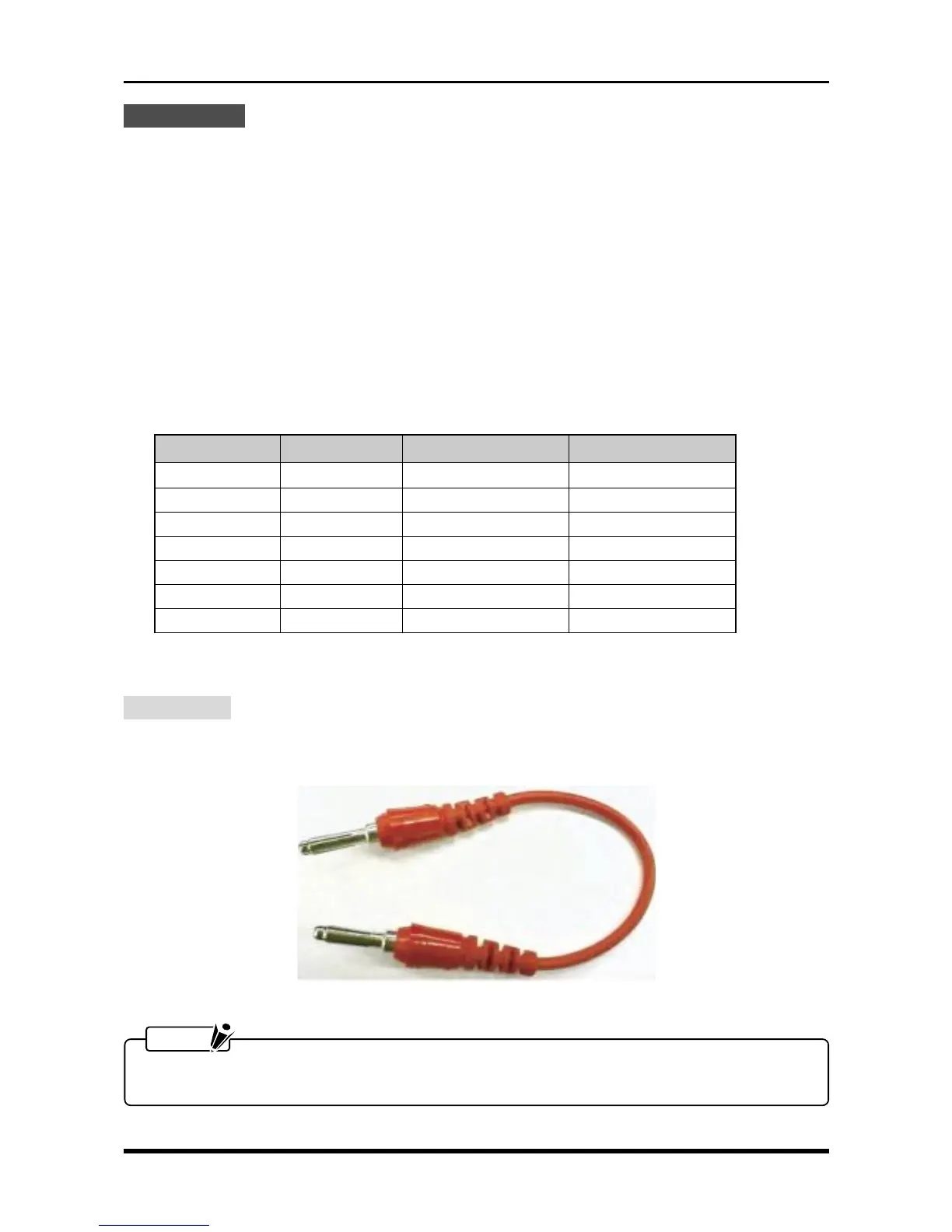
6.2.5 Signal-to-Noise Ratio
Preparation
Prepare the short terminals shown below for shorting the + and
-
terminals for each channel of the target amp,
then short those terminals.
Fig. 6-2-8
NOTE
If there are not enough short terminals to short each channel separately, set the RANGE setting for each
of that amp’s channels to Off.
Temperature value Input voltage Standard 1 Standard 2
–200°C –5.603 mV –202.5°C to –197.5°C –203.0°C to –197.0°C
–100°C –3.379 mV –102.5°C to –98.0°C –102.5°C to –97.5°C
0°C 0.000 mV –1.5°C to 1.5°C –2.0°C to 2.0°C
100°C 4.279 mV 98.3°C to 101.7°C 97.8°C to 102.2°C
200°C 9.288 mV 198.1°C to 201.9°C 197.6°C to 202.4°C
300°C 14.862 mV 297.9°C to 302.1°C 297.4°C to 302.6.°C
400°C 20.872 mV 397.7°C to 402.3°C 397.2°C to 402.8°C