WR1000-UM-251–01–9380 4 – 6
4. SETUP PROCEDURES
(8) When the prompt below appears, individually set the measurement precision for each range. Specify the
voltage generator’s output voltage setting to correspond to one of the displayed voltage Ranges in the
following table, and then input that voltage to the WR1000.
20mV:
[
Start
]
to exec.
Fig. 4-5-4
Table 4-5-1
Displayed Range setting Output voltage setting
20 mV 20.00 mV
50 mV 50.00 mV
100 mV 100.0 mV
200 mV 200.0 mV
500 mV 500.0 mV
1 V 1.000 V
Sequentially repeat Steps (7) and (8) for each Range listed in the preceding table, from 20mV through 1V.
(9) When you have finished the Setup operation for 1V, the prompt below appears.
EEPROM :
[
Exec
]
to start
Fig. 4-5-5
(10) Press the
EXECUTE
key at the Conditions panel to begin writing the new Setup data to the EEPROM of
each amp.
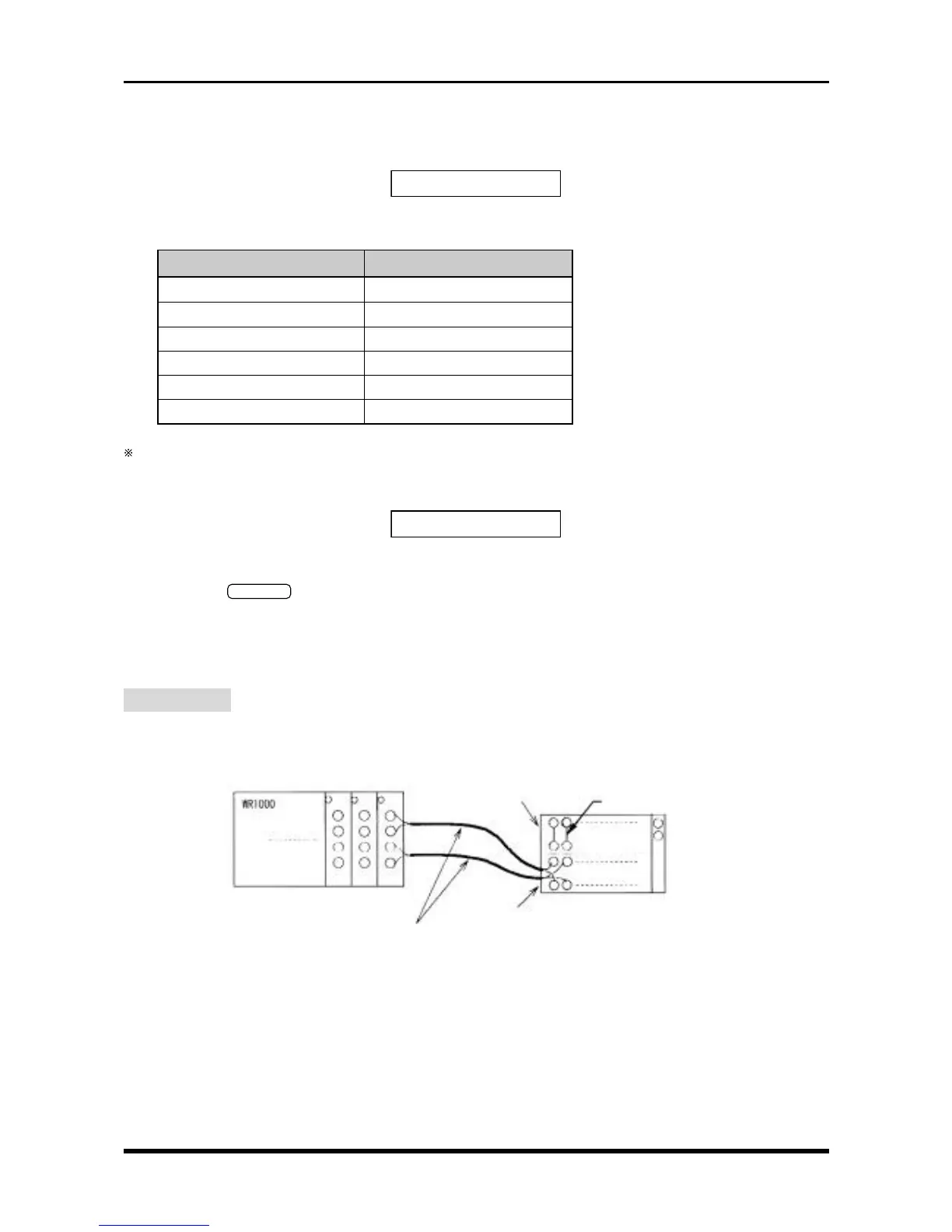
4.5.2 Setup 2 (Temperature)
Preparation
As shown below, use (T) temperature compensation leads to connect the target amps to a 0°C reference
temperature device (zero control). Also be sure to use (T) temperature compensation leads to connect M type
amps to each other.
CAUTION : Connect each compensation copper lead to a single terminal as shown in the
above diagram (parallel wiring is not permitted).
Fig. 4-5-6. Connection to a 0°C reference temperature device (zero control)
(T) compensation copper leads
(T) output side
Short the + and
-
terminals
+
-
+
-
(T) input side
0°C reference
temperature device
(zero control)