WR1000-UM-251–01–9380 6 – 28
6. INSPECTION AND CHECK PROCEDURES
NOTE
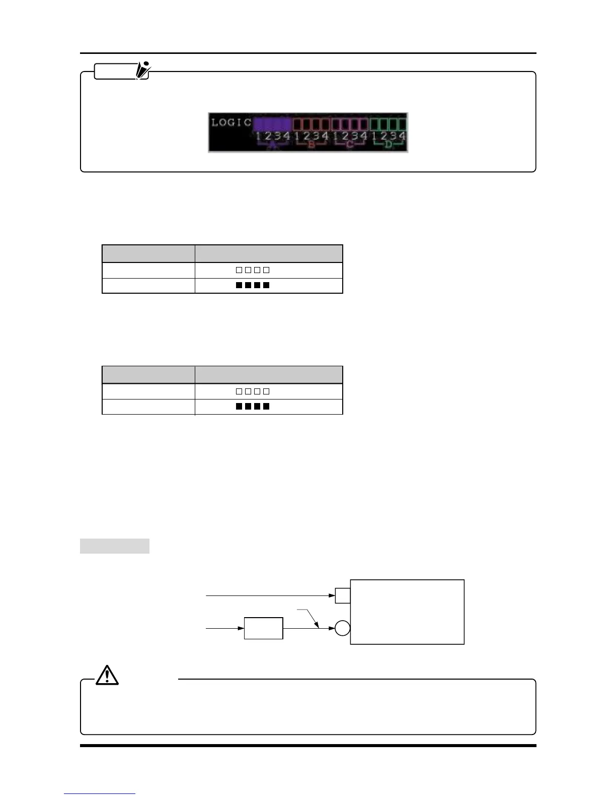
A Logic Group that is properly set up for measurement (Group D in this example) is indicated in the Logic
display area as shown in the figure below.
Fig. 6-3-4
(5) Change the Threshold level to +2.5V (CMOS) in the AMP Settings window, then check that the measured
results conform to those in the “Results” column in the table below when each specified voltage is input
to the logic input terminals.
Table 6-3-2. When the Threshold level is +2.5V (CMOS)
Input voltage Results (A, B, C, and D)
2 V
(
LLLL
)
3 V
(
HHHH
)
(6) Change the Threshold level to +5.0V (Contact) in the AMP Settings window, then check that the mea-
sured results conform to those in the “Results” column in the table below when each specified voltage is
input to the logic input terminals.
Table 6-3-3. When the Threshold level is +5.0V (Contact)
Input voltage Results (A, B, C, and D)
4 V
(
LLLL
)
6 V
(
HHHH
)
6.3.3 Expansion Memory Board
To check the operation of the expansion memory board, repeat the procedure described in Subsection 6.2.7,
“Memory Trigger Operation,” but substitute the settings for the optional memory instead of for the standard
memory.
6.3.4 DC Adapter Operation
Preparation
Respectively connect the WR1000’s AC line inlet (AC IN) and DC jack as shown in the figure below.
AC IN
WR1000
DC IN
100 VAC (200 V)
100 VAC
+12 VDC or +24 VDC
DC power
source
Fig. 6-3-5
CAUTION
Provide a DC power source that is capable of outputting the voltage and current specified below.
Voltage : +12 VDC or +24 VDC
Current : 20 A (maximum)